hahahahahaha I will do so. 🙂 I first want to get everything before building a chassis because I order XLR and RCA input boards to, so that needs t be design into the rear of the unit to. I'm maybe thinking to add Valve input stage to.Patience, dear Gerlach, patience. Meanwhile you have lots of things to do. Assemble the chasis first.
Dear Berlusconi! i have bought pcb from china, and am about to build A60. I have read many of your articles about this. There are a few issues I hope you can help me with:
1. Do you use A970/C2240 rank BL or GR? I don't have A970/C2240 so I use A992/C1845, does it affect the sound much?
2. the transistors need to be matched in pairs according to the schematic?
3. Can 47R resistor be replaced by 51R?
(Because I don't know English, I should use Google translate, if there are any mistakes, please forgive me). Thank you!
Welcome aboard Danghunglshb 😎
Don't worry, your English is flawless - we understand each other. Just look around the world how many variants of English exist but it is important that it serves the purpose of enabling communication.
For this project I use CDIL TCSA970GR/TCSC2240GR (made in India) and I was able to achieve low THD+N values. It is rational to conclude that they produce adequate semiconductors from practical point of view. Some people believe unfounded gossip/prejudices, I believe in measurements.
I have also tried with OnSemi KSC/KSA "close" equivalent semiconductors but in this particular case, CDIL was adequate, according to measurements.
All SA970GR measured hfe about 300, uniformly, with slight deviations.
The most of SC2240 had hfe 288 with few exceptions up to 335.
Interestingly, I was able to match transistors reasonably close although "complementary" transistors are often complementary just by name. But I believe that this amplifier isn't sensitive to slight mismatch. I have also several "finished" boards from China and I don't think they were wasting time with matching. Yet these boards measure well and sound fine. So I believe that some strict matching is not so important.
I am not sure about the possibility of replacing 47R resistor with 51R. I dont think that would have some noticeable impact.
Please, do not hesitate to ask in future. I would like to be helpful.
Dear Berlusconi! i have bought pcb from china, and am about to build A60. I have read many of your articles about this. There are a few issues I hope you can help me with:
1. Do you use A970/C2240 rank ? I don't have A970/C2240 so I use A992/C1845, does it affect the sound much?
2. the transistors need to be matched in pairs according to the schematic?
3. Can 47R resistor be replaced by 51R?
(Because I don't know English, I should use Google translate, if there are any mistakes, please forgive me). Thank you!

Thanks for your instructions. I will soon assemble it with A992/C1845 (hfe around 400) with 1 pair of output power per channel for testing. When it's done, I'll report back...😀😀😀
@Berlusconi they have arrived 😁 Now I need to prep and cut the heatsink to size and start building and design enclosure.
Attachments
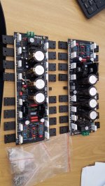
Great news indeed 👍@Berlusconi they have arrived 😁 Now I need to prep and cut the heatsink to size and start building and design enclosure.
And don't forget to use current limiting and short circuit protection. You've waited too long to burn it at the start-up.
Keep us informed about your progress.
Hi, I'm just purchased the A60+, and completed the assembly. May any advice on what is the optimum value for the quiescent current adjustment VR from 20 ~ 30mV? and what is the impact of lower of higher mV selection ?
Hi garfieldso,
Firstly, welcome on board.
I have tried all possible settings from 20 to 60 mV. The increase from 20 to 30 mV has more pronounced impact both on THD and sound quality. On the other hand increase from 50 to 60 mV has just a marginal contribution at the cost of signifficant temperature rise. So the sweet spot is somewhere from 30 to 40 mV.
However, it all depends on your heat sinks. As usually I use 0.3 K/W radiators and I was able to safely adjust the quiescent current whilst observing temperatures on all individual output devices.
Therefore my advice is to first burn-in your amplifier over a week or so at lower levels. After that period you may start to gradually increase the quiescent current while observing temperature. Turning in the counterclock direction increses the QC. Stop at 45° to 50° or even earlier if it results in good sound quality but never let temperature rise to higher values. Note that after the increase of the QC temperature will rise but the actual QC value will decrease and then stabilize at some lower value.
In short: Don't push too hard.
Good luck
PS: Meanwhile I have improved my THD measuring rig and will make more measurements somewhere in Januarry and will get back with more data. However note that this amplifier doesn't have infinitesimally small THD but contribution of the dominant 2nd harmonic makes its sound so convincingly good. It simply sounds right to my ears.
Hi Berlusconi,
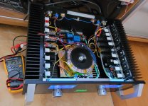
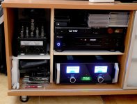
Thank you so much for your detailed explaination, very useful. I am using an old chassis to fit in the board, however the length of case is marginal to fit in, and the heatsink fins is around 2 inches thichness. Therefore the heat dissipation may not be sufficiently for higher quiescent current upto 50~60mV. I will follow your instruction to burn in a week and observe the temperature level, I started up at 25mV.
Thank you so much for your detailed explaination, very useful. I am using an old chassis to fit in the board, however the length of case is marginal to fit in, and the heatsink fins is around 2 inches thichness. Therefore the heat dissipation may not be sufficiently for higher quiescent current upto 50~60mV. I will follow your instruction to burn in a week and observe the temperature level, I started up at 25mV.
Attachments
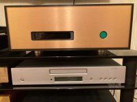
Yes, it is a Mac-look case, as it is small enough to fit in my cabinet housing. The FM case is really in nice outlook. By the way the front window is what purpose?Macintosh case? At first I also wanted one, but I bought FM Acoustics. I'm going to shove it there.
Last edited:
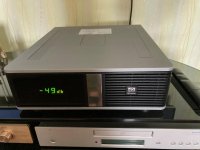
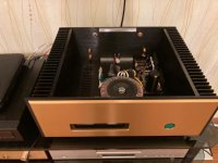
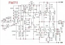
I wanted to switch to the FM Acoustics 411(711) project, but after looking at the diagrams and following the advice of smart guys, I have not decided yet. I thought about inserting the A60 into this beautiful case, which I like in terms of sound. What will my dear GURU say? The schemes are not much different. Does it make sense to do 411 (711)?
Attachments

Hi guys,
Congratulations for really beautiful amplifiers. Also, I'm glad to see my good old friend Paroxod again. It is fine to be in company of nice guys.
Right now I work on some other projects but I will get back to my A60 amplifiers to make more meassurements with my new THD meassuring rig with improved noise flor.
I have an idea how to meassure heat dissipation of our A60s. It is enough to perform two basic meassurements: (1.) meassure voltage across the collector and emitter and then (2.) voltage across emitter resistor. By using Ohms law we can calculate current through the transistor. Dissipation can be then calculated as a product of emitter-collector voltage and current.
This simple meassurement can be performed at different quiescent current values and power levels to find correlation among QC, output power and heat dissipation. This meassurements may help to find safe limits on QC and output power.
P.S. (Meanwhile Paroxod has posted #376).
Take them both. I also experiment with more amplifiers. Regatding this I am polygamic. After having them all I will know which are the best and have fun of testing them all. The same as that joke about the Father Bull ans Son Bull at the top of the hill observing a cattle of the cows in the walley.
Last edited:
garfieldso
Do not be afraid. Your radiators are normal. I set it 2 times less, the temperature is 70 degrees at 25 mV (I set it with protection for experiments), 4 hours of loud music is the norm.BerlusconiI I didn’t disappear anywhere. In search of a beautiful case, I came across another amplifier. It was very expensive. But I liked the case. Then I looked at the 711 boards and circuits, I wanted to do something (this is in the project). our A60 amplifier (he has a bomb sound) with a volume control and a display.:)

- Home
- Amplifiers
- Solid State
- A60(+) Amplifier. Build this?