The best impedance calculator I know is this one:
Impedance Equalization (L-Pad) Circuit Designer / Calculator
You just need the Le and the DCR.
But this is all very confusing, jing. 🙂
What drivers and crossover components and cabinets do you actually HAVE?
Two mismatched woofers sound like trouble to me.
A series filter might be a fun idea here, and sometimes it can all play nicely.
It's not hard to do a 2.5 way aka TMM, or an MTM.
The series filter below plays nicely in either configuration. You can just move the 0.5 woofer about. It doesn't even need component changes. The parallel MTM filter looks easy enough too. All a bit driver dependant, of course. High woofer Le makes for problems which usually need shunt resistance to damp.
You can also do a three way with two identical or similar woofers. A resistive pad (which corrects rising impedance) in front of the midrange can make this easy. But padding down a bass woofer is not straightforward. I'd be looking at the two woofers to decide which one does which job best.
Attachments
Hmm, so it's the other way around, the 0.5 is more sensitive. Compensation should be taken sparingly as it is imperfect to begin with - here you'll be overshooting the mark without due care.
Many would say don't use resistors or resonance impedance correction on woofers because it's wasteful of power, expensive and a generally untidy solution at best. I tend to feel it is OK to do if you have a good reason...?
I can see a way out of this if you allow the higher sensitivity to abound below approximately 100Hz, shelving the 0.5 a little through the compensation region and dropping off again above that. Depending where the step is this might be calling for a compound shelving system.
I agree with Steve, it isn't simple anymore. But in situations like this you might be surprised what you can hear and what you can't, what does work and what doesn't even though it either makes sense or not.
Thanks, tbh this is a project revising a existing tmm design as following:The best impedance calculator I know is this one:
Impedance Equalization (L-Pad) Circuit Designer / Calculator
You just need the Le and the DCR.
But this is all very confusing, jing. 🙂
What drivers and crossover components and cabinets do you actually HAVE?
Two mismatched woofers sound like trouble to me.
A series filter might be a fun idea here, and sometimes it can all play nicely.
It's not hard to do a 2.5 way aka TMM, or an MTM.
The series filter below plays nicely in either configuration. You can just move the 0.5 woofer about. It doesn't even need component changes. The parallel MTM filter looks easy enough too. All a bit driver dependant, of course. High woofer Le makes for problems which usually need shunt resistance to damp.
You can also do a three way with two identical or similar woofers. A resistive pad (which corrects rising impedance) in front of the midrange can make this easy. But padding down a bass woofer is not straightforward. I'd be looking at the two woofers to decide which one does which job best.

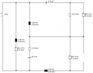
With hp l=0.375 mh, lp l=0.483 mh.
Tweeter is audax tw025 m0
woofers are audax at170g0
Now i am not happy with the sound and thinking to upgrade one of thne woofes to hivi f6 and put the other to a real 0.5 leg.
Last edited:
wolf_teeth found that about 2mH total plus the Le 1.8mH was about right:
Nephila | Parts Express Project Gallery
You misunderstand what is going on in the Nephila circuit. The 1st coil (1.5mH) is the lowpass providing tilt to flatten out the response below Fc, and the second coil (0.47mH) is in a notch to suppress the resonance the driver has at about 900 Hz. Since the 47uF cap is across the 0.47mH coil, that combined with the resistor only dips the response a bit in between the Fc's of those 2 parts and does not provide further rolloff.
You really shouldn't look at that as a 2mH lowpass coil.

Later,
Wolf
I can answer that Alan. It's a notch at 13kHz for the lively amount of HF hash the HiVi F6 woofer puts out:
Overview F6 Bass-Midrange_HiVi, Inc.
The total bafflestep coil in wolf's circuit IS 1.5mH plus 0.47mH. The 0.47mH has an effect on tilt below 1kHz. Sim it and see. 🙂
But really I just wanted to get a feel for the correct value here if that HiVi F6 gets used.
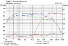
I was doing some fiddling around with some options this afternoon. I was slightly disturbed that the series filters hit the tweeter level quite hard. This is because the always need a resistor in the shunt for good impedance. Definitely 4dB loss. It's marginal whether it'll work.
I don't see any case for changing the Audax woofers here, though I can't even find a frequency response for the audax at170g0. What is it made of, cone-wise?
I don't see any case for the 2.5 circuits either. This isn't the issue IMO.
So I looked at what we could do to tidy up the parallel circuit. There's two ways to do a 5-6kHz notch, useful with 6" bass. The series filters look quite tidy too, but don't really look much better. A 22R across the tweeter must be good too for the highish Fs resonance. BTW, if your value of coil is 0.91 mH, I'd use a 1mH. Gotta be easier to find.
It's up to you whether that is doing the right things tonally.
Overview F6 Bass-Midrange_HiVi, Inc.
The total bafflestep coil in wolf's circuit IS 1.5mH plus 0.47mH. The 0.47mH has an effect on tilt below 1kHz. Sim it and see. 🙂
But really I just wanted to get a feel for the correct value here if that HiVi F6 gets used.
I was doing some fiddling around with some options this afternoon. I was slightly disturbed that the series filters hit the tweeter level quite hard. This is because the always need a resistor in the shunt for good impedance. Definitely 4dB loss. It's marginal whether it'll work.
I don't see any case for changing the Audax woofers here, though I can't even find a frequency response for the audax at170g0. What is it made of, cone-wise?
I don't see any case for the 2.5 circuits either. This isn't the issue IMO.
So I looked at what we could do to tidy up the parallel circuit. There's two ways to do a 5-6kHz notch, useful with 6" bass. The series filters look quite tidy too, but don't really look much better. A 22R across the tweeter must be good too for the highish Fs resonance. BTW, if your value of coil is 0.91 mH, I'd use a 1mH. Gotta be easier to find.
It's up to you whether that is doing the right things tonally.
Attachments
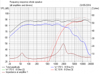
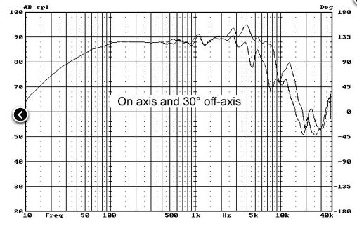
I dug up the woofer eventually. It's similar to the shielded paper Audax AT 170 M0 apparently. Low inductance LE 0.22mH though the curve is talking to me of 1.2mH, DCR around 6 ohms, Qts around 0.69 so big closed box I suppose.
http://www.cadaudio.dk/audaxunits.htm
Bit of a bump there at 4kHz.
http://www.cadaudio.dk/audaxunits.htm
Bit of a bump there at 4kHz.
Attachments
Last edited:
I can answer that Alan. It's a notch at 13kHz for the lively amount of HF hash the HiVi F6 woofer puts out:
Overview F6 Bass-Midrange_HiVi, Inc.
The total bafflestep coil in wolf's circuit IS 1.5mH plus 0.47mH. The 0.47mH has an effect on tilt below 1kHz. Sim it and see. 🙂
Apparently you still don't know what's going on, Steve. The 0.1uF allows for a 'broad notch' for the out of bandwidth freq's which can help the rolloff become steeper to start with. There is not really a "lively amount of HF hash the HiVi F6 woofer puts out." As a matter of fact, I'm allowing the ripples in the FR up to almost 3.5k to play just as they are. It sounds really nice and does not need to be hindered and xovered lower. This was only a means to rolloff the out of bandwidth frequencies. This is also called a tank-notch.
And no- it does not change the BSC comp much if at all for that notch. I modeled it myself:

The notch is for the resonance at about 900-1100 Hz region only, and does not steepen or tilt the FR in general. It only reduces the magnitude of the resonance, and is no way used to comp for BSC. You can see the impedance spike in the gradual inductive rise of the woofer + xover.
Sorry for the departure from the thread direction, but this did need to be corrected.
Later,
Wolf
Thanks so much for helping. Really appreciate it.I can answer that Alan. It's a notch at 13kHz for the lively amount of HF hash the HiVi F6 woofer puts out:
Overview F6 Bass-Midrange_HiVi, Inc.
The total bafflestep coil in wolf's circuit IS 1.5mH plus 0.47mH. The 0.47mH has an effect on tilt below 1kHz. Sim it and see. 🙂
But really I just wanted to get a feel for the correct value here if that HiVi F6 gets used.
I was doing some fiddling around with some options this afternoon. I was slightly disturbed that the series filters hit the tweeter level quite hard. This is because the always need a resistor in the shunt for good impedance. Definitely 4dB loss. It's marginal whether it'll work.
I don't see any case for changing the Audax woofers here, though I can't even find a frequency response for the audax at170g0. What is it made of, cone-wise?
I don't see any case for the 2.5 circuits either. This isn't the issue IMO.
So I looked at what we could do to tidy up the parallel circuit. There's two ways to do a 5-6kHz notch, useful with 6" bass. The series filters look quite tidy too, but don't really look much better. A 22R across the tweeter must be good too for the highish Fs resonance. BTW, if your value of coil is 0.91 mH, I'd use a 1mH. Gotta be easier to find.
It's up to you whether that is doing the right things tonally.
The reason i am replacing one of the woofers are, first, it is broken, and, I would like to try f6 for its sweet midrange, and also, i dont undetstand that two woofers in parallel in terms of what benefit i am getting.
Sent from my HUAWEI MT7-TL10 using Tapatalk
Not much really. Although it gives you one way of compensating the baffle region there is nothing special about it in my opinion. I've tried it and it does that particular job well, but really you'll just get a slight increase in the maximum bass output.i dont undetstand that two woofers in parallel in terms of what benefit i am getting.
Multiple drivers can also be used to alter the directivity but hardly, in your case, and especially when configured for 2.5 way.. so all you really get is the extra cone area to move a little more air.
Thanks Allen, So it is hardly 2.5 way then?Not much really. Although it gives you one way of compensating the baffle region there is nothing special about it in my opinion. I've tried it and it does that particular job well, but really you'll just get a slight increase in the maximum bass output.
Multiple drivers can also be used to alter the directivity but hardly, in your case, and especially when configured for 2.5 way.. so all you really get is the extra cone area to move a little more air.
How about two different woofers? Not sure it will change or damage anything?
Sent from my HUAWEI MT7-TL10 using Tapatalk
Not sure what you mean by this.Thanks Allen, So it is hardly 2.5 way then?
In many ways acoustically, the model of driver is not very significant. In some respects this is one case where that is so.How about two different woofers? Not sure it will change or damage anything?
Where it may matter is with your need to have the drivers working together which means that they should have similar sensitivities (or have some useful relation anyhow), be able to work within the range of choice and have electrical characteristics that suit parallel operation.
Damage? Probably not.
I meant the original design i attached here is not actually a 2.5 way as it has two woofers in parallel.Not sure what you mean by this.
In many ways acoustically, the model of driver is not very significant. In some respects this is one case where that is so.
Where it may matter is with your need to have the drivers working together which means that they should have similar sensitivities (or have some useful relation anyhow), be able to work within the range of choice and have electrical characteristics that suit parallel operation.
Damage? Probably not.
If it does its job well, i might keep them untouched or i need to design a new .5 way?
Sent from my HUAWEI MT7-TL10 using Tapatalk
There is very little difference between a two woofer two way design, and a 2.5 way. The box can be the same and only the crossover need be different. You can try both with just a little rewiring.
Eg: The 2.5 way might use a first order rolloff on one driver and the normal crossover on the other with the overall circuits in parallel.
The two woofer two way might have both drivers in parallel with compensation and the normal crossover applied to both at the same time.
Using two different units might be more of a problem at higher frequencies so that might go toward the 2.5 way, but honestly, why not give both a try and start discovering what you like about each driver.
Thanks Allen,There is very little difference between a two woofer two way design, and a 2.5 way. The box can be the same and only the crossover need be different. You can try both with just a little rewiring.
Eg: The 2.5 way might use a first order rolloff on one driver and the normal crossover on the other with the overall circuits in parallel.
The two woofer two way might have both drivers in parallel with compensation and the normal crossover applied to both at the same time.
Using two different units might be more of a problem at higher frequencies so that might go toward the 2.5 way, but honestly, why not give both a try and start discovering what you like about each driver.
i shall certainly have both ways tried.
At moment i am yet to order the big inductor for the 0.5 way from PE. (How big is enough?)
I will try double woofers with different specs first.
Cheers
Sent from my HUAWEI MT7-TL10 using Tapatalk
Last edited:
Hi, Steve,I dug up the woofer eventually. It's similar to the shielded paper Audax AT 170 M0 apparently. Low inductance LE 0.22mH though the curve is talking to me of 1.2mH, DCR around 6 ohms, Qts around 0.69 so big closed box I suppose.
http://www.cadaudio.dk/audaxunits.htm
Bit of a bump there at 4kHz.
which one do you think better? The f6 or at170 m0?
Cheers
Sent from my HUAWEI MT7-TL10 using Tapatalk
Which one is better?
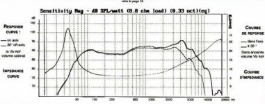
Audax AT 170 M0 or G0, Qts 0.68:

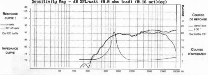
HiVi F6, Qts 0.35:
Both a bit peaky at 4kHz, best having a notch around 6kHz IMO.
PEERLESS-NOMEX-164
I'm most bothered about the difference in Qts, lumpy bass and difference in level. I really don't know how that will pan out. Is this a common enclosure (closed box) around 40L?
For a series filter tending to 2.5 way, I'd be happier with a smoother polycone like the Peerless 830874.
TBH, I'm not ready to go on this yet. So many problems. 😕
Audax AT 170 M0 or G0, Qts 0.68:
HiVi F6, Qts 0.35:
Both a bit peaky at 4kHz, best having a notch around 6kHz IMO.
PEERLESS-NOMEX-164
I'm most bothered about the difference in Qts, lumpy bass and difference in level. I really don't know how that will pan out. Is this a common enclosure (closed box) around 40L?
For a series filter tending to 2.5 way, I'd be happier with a smoother polycone like the Peerless 830874.
TBH, I'm not ready to go on this yet. So many problems. 😕
Attachments


Hi steve,Which one is better?
Audax AT 170 M0 or G0, Qts 0.68:
HiVi F6, Qts 0.35:
Both a bit peaky at 4kHz, best having a notch around 6kHz IMO.
PEERLESS-NOMEX-164
I'm most bothered about the difference in Qts, lumpy bass and difference in level. I really don't know how that will pan out. Is this a common enclosure (closed box) around 40L?
For a series filter tending to 2.5 way, I'd be happier with a smoother polycone like the Peerless 830874.
TBH, I'm not ready to go on this yet. So many problems. 😕
The box is a floorstanding 950x220 x325 with tmm setup.
Upper tm section is closed, the bottom is ported.
I will definitely go tmm with tw025m0 plus f6 plus at170g0.
So i am trying all possible ways.
2 way or 2.5 as long as it sounds good.
Thank you again.
Jing
Sent from my HUAWEI MT7-TL10 using Tapatalk
The reflex, if properly tuned is best left alone with the Audax driver. We might just hope for the best with the HiVi F6 in the closed box.
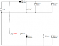
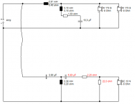
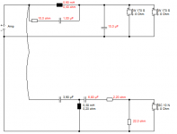
Just on general 6" bass principles I might be looking at the circuit below. Very wild guess, TBH, but recycles some components. 1mH and 10uF is right for 4 ohm load as a stock crossover. The 6kHz notch is just a good thing to do, IMO.
In a way, what you do depends on your assessment of the sound.
Just on general 6" bass principles I might be looking at the circuit below. Very wild guess, TBH, but recycles some components. 1mH and 10uF is right for 4 ohm load as a stock crossover. The 6kHz notch is just a good thing to do, IMO.
In a way, what you do depends on your assessment of the sound.
Attachments

Thank you steve.The reflex, if properly tuned is best left alone with the Audax driver. We might just hope for the best with the HiVi F6 in the closed box.
Just on general 6" bass principles I might be looking at the circuit below. Very wild guess, TBH, but recycles some components. 1mH and 10uF is right for 4 ohm load as a stock crossover. The 6kHz notch is just a good thing to do, IMO.
In a way, what you do depends on your assessment of the sound.
i see you suggest two different woofers in pair? How about the sensitivity mismatch then?
And also, will the 15ohms across the tweeter bring down its sensitivity too?
Cheers,
Sent from my HUAWEI MT7-TL10 using Tapatalk
- Status
- Not open for further replies.
- Home
- Loudspeakers
- Multi-Way
- A two way 2nd order series crossover design