This program is pretty good for visualizing diffraction and baffle step effects, and even shows filter circuits to help remedy them.
Home of the Edge
Mike
Home of the Edge
Mike
I was playing with your circuit this afternoon, jing.
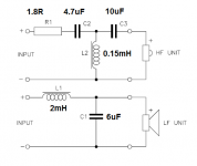
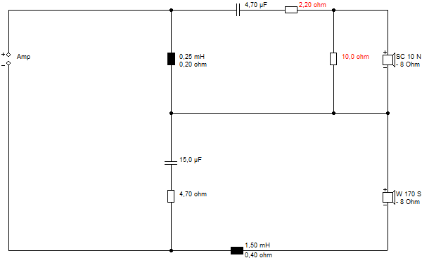
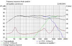
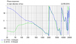
I don't think you need such a low crossover. The B&W Matrix 805 uses a Kevlar bass on a near 3kHz crossover. I found the circuit below was quite similar with a near 2.5kHz crossover. Seems to cure the midrange bump or shout.
Bigger 1.5mH coil, and 15uF and 0.25mH rather than 22uF and 0.47mH. I moved the resistor too. It gives better rolloff to the bass.
You're always going to get a bit of cone breakup at 4-5kHz, but no worse than the Matrix 805 IMO. You'll have to model tweeter level.
For such a simple circuit, there is a lot to like.
Attachments

Last edited:
Thanks for this. I d love to try this.I was playing with your circuit this afternoon, jing.
I don't think you need such a low crossover. The B&W Matrix 805 uses a Kevlar bass on a near 3kHz crossover. I found the circuit below was quite similar with a near 2.5kHz crossover. Seems to cure the midrange bump or shout.
Bigger 1.5mH coil, and 15uF and 0.25mH rather than 22uF and 0.47mH. I moved the resistor too. It gives better rolloff to the bass.
You're always going to get a bit of cone breakup at 4-5kHz, but no worse than the Matrix 805 IMO. You'll have to model tweeter level.
For such a simple circuit, there is a lot to like.
The only thing is that your drivers have diffrrent specs so the numbers might not fit mine.
Talking about numbers, i am realy confused these days. As they say Xsim is close to 100% accurate, i was changing these values, caps, resistors and inductors, but it appears to me these changes don't affect the curve too much, sometime even 1uf change means nothing.
So a 10% tolerance cap may be just as good as 1% one. Replacing a 2ohms resistor with 4.7 one might hurt nothing.
Imho of course.
Sent from my HUAWEI MT7-TL10 using Tapatalk
Thanks for the reply. I am think to use a hybrid one, 1st in lp, 2nd in hp, as i put in another post you have replied too.Hi,
That is true for 1st order series *, but exactly the opposite for 2nd order.
The point is whether the final x/o component is in parallel or series with
the drivers. Parallel is what you want, and is true for odd order series,
and true for even order parallel.
Therefore for 2nd order electrical you choose parallel.
And read up on diffraction / baffle step effects, your ignoring them.
rgds, sreten.
* 1st order series has limited use but is ideal for FAST's
with well chosen drivers, with different sensitivities x/o
at or near the baffle step mid frequency.
Series is worth trying I think.
As to bsc, do you think a 3.3mh inductor in parallel will do the job?
I see a lot 2.5 ways with that setup.
Cheers
Sent from my HUAWEI MT7-TL10 using Tapatalk
I think you're getting baffled by bafflestep here, my friend. It is of course where at below a certain frequncy, usually around 1kHz, the bass leaks away round the back of the speaker and loses effective volume.
You just add a coil to the woofer to accomplish the required bass boost. Which you did.
I just had the feeling your 0.9mH was a bit small, but it's may just make for a speaker that works best close to a wall. In practise, the full 6dB bafflestep boost is usually too much. I was using a 20cm wide cabinet. It's one of those things you can adjust on listening.
As a learning or teaching exercise - what you are doing is good as you are learning the process and mechanics of designing a crossover. The effects of baffle step loss and diffraction on a typical 8in to 12in wide box is going to be of order 5dB. So designing a xo this way will get you an approximate starting point within 5dB. That may be good enough but you will need to make a measurement on the actual baffle with the actual drivers to get the phase information so that you can set the correct time/phase alignment so that at the XO region the signals combine as you expect.
The process you are doing now is good to get a rough idea of whether or not the driver is a suitable fit from the standpoint of sensitivity and frequency response. It will allow you to make a decision of whether or not buy the driver. Once they show up mount them in the box and make the real measurement with a calibrated mic. You need 3 measurements: one with just woofer connected, one with just tweeter connected, a one with both in parallel. It's critical that all 3 measurements are made without physically moving the speaker or mic - just switch wires carefully. The import the minimum phase FRD files into Xsim (or PCD - another excellent tool by Jeff Bagby). The data now gives you info to use acoustic interferometry to calculate the acoustic offset (distance from where the voice coil source of the sound originates relative to each other) exactly to 1mm accuracy. This is needed to design the xo phase response properly.
So don't abandon what you are doing with tracing FR plots from manufacturer if you are still in the search mode for drivers. If you have already bought drivers and MUST use them, then the next step is to make measurements in the as-built baffle or box.
Thanks for the reply. I will use a .5 way to do the baffle step compensation. The baffle is 22cm wide, some say I will need 6db?
Cheers,
As system7 says, it's a little less simple than that. What happens to that bass that leaks around the cabinet?
Thanks. But this appears a 2nd order sxo?I think you're getting baffled by bafflestep here, my friend. It is of course where at below a certain frequncy, usually around 1kHz, the bass leaks away round the back of the speaker and loses effective volume.
You just add a coil to the woofer to accomplish the required bass boost. Which you did.
I just had the feeling your 0.9mH was a bit small, but it's may just make for a speaker that works best close to a wall. In practise, the full 6dB bafflestep boost is usually too much. I was using a 20cm wide cabinet. It's one of those things you can adjust on listening.
I am thinking put a 3mh inductor and a zobel plus woofer to do the job.
I tried to simulate your idea, but hard to get the right curve.
What is more, i think two woofers would sound tighter in bass.
Jing
Sent from my HUAWEI MT7-TL10 using Tapatalk
Thanks. But this appears a 2nd order sxo?
...snip
What? And this one ISN'T? 🙄

Very slow progress here, my friend. 😀
Yes, both are 2nd sxo. So i am not sure im that case where the bsc is coming from.
What? And this one ISN'T? 🙄
Very slow progress here, my friend. 😀
Sent from my HUAWEI MT7-TL10 using Tapatalk
It's coming from the combination of the voicecoil inductance and the bass coil. About Le 1.8mH plus 0.9mH in your case.Yes, both are 2nd sxo. So i am not sure im that case where the bsc is coming from.
Sent from my HUAWEI MT7-TL10 using Tapatalk
wolf_teeth found that about 2mH total plus the Le 1.8mH was about right:
Nephila | Parts Express Project Gallery
Bafflestep messes series filters up a bit from the theoretical optimal ratios. If you separate it out with an RL passive bafflestep sometimes you find drivers that play very nicely together indeed. Michael Chua does this with a paralllel circuit here:
"STARLING" (Seas 27TDFC + Seas ER18RNX) Bookshelf by AmpsLab
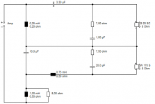
The example below works nicely because I have used calculated Zobels to correct impedance and the series filter has about 1.5kHz and 6kHz notches that suit the drivers perfectly. This is optimal time-aligned, but flat baffle is OK too.
Somebody built this one of mine and liked it, but I've never heard it. I'm theoretical. 😀
Attachments

Last edited:
This looks all nice. But i really need the 0.5 way as the speakers have 2 woofers.It's coming from the combination of the voicecoil inductance and the bass coil. About Le 1.8mH plus 0.9mH in your case.
wolf_teeth found that about 2mH total plus the Le 1.8mH was about right:
Nephila | Parts Express Project Gallery
Bafflestep messes series filters up a bit from the theoretical optimal ratios. If you separate it out with an RL passive bafflestep sometimes you find drivers that play very nicely together indeed. Michael Chua does this with a paralllel circuit here:
"STARLING" (Seas 27TDFC + Seas ER18RNX) Bookshelf by AmpsLab
The example below works nicely because I have used calculated Zobels to correct impedance and the series filter has about 1.5kHz and 6kHz notches that suit the drivers perfectly. This is optimal time-aligned, but flat baffle is OK too.
Somebody built this one of mine and liked it, but I've never heard it. I'm theoretical. 😀
And i have also found when i tried the zobel networks accoss the drivers, the response curve changed a lot.
And theoretically tweeters impedance is very flat, usually a zebol is not needed.
Cheers
Sent from my HUAWEI MT7-TL10 using Tapatalk
You can do it Steve's way with the pair in parallel if that helps?This looks all nice. But i really need the 0.5 way as the speakers have 2 woofers.
Thanks, in parallel you meant nothing but two woofers? This is what exactly my pair is. Even they are not same woofers?You can do it Steve's way with the pair in parallel if that helps?

Ok, I suppose that might change things, or not. I was saying that you can use two in the same place that you would use one, especially with woofers, not so much with tweeters, just by connecting them to each other and pretending there is one (specs change slightly of course).
Using different woofers this way can be done but I think you would need to have understood the reason you chose to do it this way. Could you be looking at a three way? Have you bought them yet? Did you get them simply to do the 2.5 way?
Using different woofers this way can be done but I think you would need to have understood the reason you chose to do it this way. Could you be looking at a three way? Have you bought them yet? Did you get them simply to do the 2.5 way?
Both woofers are midbass, and my living room is small, thereforeOk, I suppose that might change things, or not. I was saying that you can use two in the same place that you would use one, especially with woofers, not so much with tweeters, just by connecting them to each other and pretending there is one (specs change slightly of course).
Using different woofers this way can be done but I think you would need to have understood the reason you chose to do it this way. Could you be looking at a three way? Have you bought them yet? Did you get them simply to do the 2.5 way?
Oh the reason is that i bought a pair in 2.5 design with too identical woofer and i am not happy with the mid range so trying to replace one midbass and keep the rest.Ok, I suppose that might change things, or not. I was saying that you can use two in the same place that you would use one, especially with woofers, not so much with tweeters, just by connecting them to each other and pretending there is one (specs change slightly of course).
Using different woofers this way can be done but I think you would need to have understood the reason you chose to do it this way. Could you be looking at a three way? Have you bought them yet? Did you get them simply to do the 2.5 way?
Apparently a new crossover is needed for the new midbass.
But with 220mm baffle a bigger woofer in a 3 way is not poaaible.
Sent from my HUAWEI MT7-TL10 using Tapatalk
It's always tempting to force all your best things into a design just to make sure you're using them...
If I were in your position I'd be tempted to get it up and running and work towards the goal from two angles... both on paper and by listening and tweaking. Lots to learn before you rely on measurements alone, I think, and it adds to the enjoyment of the process. If you had an L and C to rig up a simple crossover, an L-pad and an extra inductor for the .5 way (most of us have a wide selection of components on hand)....
By the way, how does the sensitivity between these two different mid-woofers compare.
Yes, everything is on paper so far. But a 2way very soon. I am excited~.It's always tempting to force all your best things into a design just to make sure you're using them...
If I were in your position I'd be tempted to get it up and running and work towards the goal from two angles... both on paper and by listening and tweaking. Lots to learn before you rely on measurements alone, I think, and it adds to the enjoyment of the process. If you had an L and C to rig up a simple crossover, an L-pad and an extra inductor for the .5 way (most of us have a wide selection of components on hand)....
By the way, how does the sensitivity between these two different mid-woofers compare.
The two woofers have 2 or three db difference, therefore an lpad is needed but later with the .5 way.
Sent from my HUAWEI MT7-TL10 using Tapatalk
If the 0.5 way has the lower sensitivity you may be able to use it like that (no L-pad).
If the sensitivities were more different than that you'd have complications but it's worth a try as it is, if that's the way you want to go.
If the sensitivities were more different than that you'd have complications but it's worth a try as it is, if that's the way you want to go.
If the 0.5 way has the lower sensitivity you may be able to use it like that (no L-pad).
If the sensitivities were more different than that you'd have complications but it's worth a try as it is, if that's the way you want to go.
Thanks, yep, the 0.5 way is about 3db more sensitive and an Lpad is easy to try without even taking out the crossover, I can do it on the drivers.
Thanks for the help.🙂
- Status
- Not open for further replies.
- Home
- Loudspeakers
- Multi-Way
- A two way 2nd order series crossover design