Non-ceramic dielectrics were simply too big and too easily damaged by close-in soldering.
Tantalum caps were the standard of the day until the explosion in cell phone sales volumes created a larger demand for tantalum than could be mined.....and much of the mining was done in conflict torn countries.
Tantalum caps demand ultra high purity and careful manufacturing which was not quite perfected in the 80's hence all the bad tantalums in vintage HP and TEK gear.
Tantalum caps have their own issues and require derating the operating voltage if current flows "through" the cap. They also fail to a short, and often in spectacular flaming fashion when operated as a B+ bypass cap.
The ramp up in cell phone volume drove the development of new ceramic caps.
How about the modern so called "MLC" ceramics?
MLC is Multi Layer Ceramic, pretty much the standard way to get large capacitance in a small volume. Multiple extremely thin alternating layers of metal and ceramic. Yes, the technology was developed for phones which run from a single cell lithium polymer battery. The B+ voltage is 3.4 to 4.2 volts and major subsections usually run on 3.3 and 1.8 volts with the CPU cores usually around one volt.
The big CPU chips found in our PC's also operate in the same voltage ranges.
I have seen some fairly large SMD ceramic caps in the 100 and 250 volt range. They were intended for high power RF transmitters.
I have some surface mount film caps - they just melt when I try to solder them in place...
Those critters are far too easy to melt. I usually but solder paste on the pads, drop the cap in the solder, and heat the board from the back side on a hot plate. As soon as the solder reflows move the board off the heat and onto a heat sink.
Tantalum caps have their own issues and require derating the operating voltage if current flows "through" the cap. They also fail to a short, and often in spectacular flaming fashion when operated as a B+ bypass cap.
The same with high capacitance density ceramic caps. Back in 1970'Th I used Soviet military KM-4, KM-5 and KM-6 caps to shunt power near opamps, and had couple of times when they failed short. Pretty rare, but still. Then I started to routinely add 10 Ohm resistors before each of them, it was a PITA to find which one is short. Also, resistors decreased ground loop problems.
The same with high capacitance density ceramic caps.
Tantalums burst into flames and often send flaming shards of tamtalum in multiple directions. Ceramics just EXPLODE! Tantalums can fail when operated at less than half rated voltage if the circulating current is high enough (B+ bypass on TDMA RF power amp). Ceramics can often eat 2 or 3 times their rated voltage before BANG happens.
it was a PITA to find which one is short.
I used to find them with a BIG power supply. (see above). The PCB traces must be fat enough to eat the short circuit current of said big power supply.
I just got an email flyer from a surplus company. They have some surplus leaded MLC 0.1 uF capacitors rated for 500 volts. They are 0.4 inch lead spacing and about 0.3 inches tall. If I order anything from them before the sale ends, I may get a few to play with.
I used to find them with a BIG power supply. (see above). The PCB traces must be fat enough to eat the short circuit current of said big power supply.
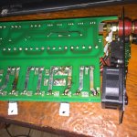
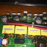
Today's find, by the way.
What's the point in 3x30A fuses in parallel when traces burn before them? 😀
And how the hell 50V rated at 105 degrees caps get almost exploded from 12V solar panels?
Attachments
Last edited:
You guys are jacking this thread...
Sorry. No caps' talks anymore. Zipped. 😉
You guys are jacking this thread...
i am happy, a capacitor thread that did not end up like the others....😀
some very good ideas were exposed here....let us keep them coming...😎
And how the hell 50V rated at 105 degrees caps get almost exploded from 12V solar panels?
It's from the large circulating current (rapid charge / discharge) caused by the inverter that those caps are feeding. The solar cells are feeding a (relatively) constant current flow into the caps, but the switching devices draw current from these caps in pulses surround by dead time (no current flow). This results in power being dissipated in the cap's ESR and ESL.
The same thing happens to the bulk line caps in an SMPS and to the 12 volt input caps in a big car audio amp.....hence the 1 farad and up "stiffening cap".
You are right, they were inadequate for the rating of the inverter that produced 280W at the sunniest day, the same as PCB traces in it. Epic designers from solarepic.com 😀
I bought a replacement inverter, and shunted the panels by a huge US made blue 100,000uF 30V cap (40V surge).
PS: sorry for the cap talk, I just answered. 😀
I bought a replacement inverter, and shunted the panels by a huge US made blue 100,000uF 30V cap (40V surge).
PS: sorry for the cap talk, I just answered. 😀
Back in the day, a cell phone manufacturer could not get enough cell phone testers from their favorite T&M company.
So they asked the T&M co.: "Why did the cell phone testers have such a long lead time"?
The T&M co. said: "They could not get the capacitors needed to make the cell phone testers.
The cell phone manufacturer asked which kind(s) of capacitors, got the answer, and shipped the needed capacitors to the T&M company.
One cell phone tester can test thousands of cell phones.
A few less cell phones = plenty of cell phone testers.
After that, a plethora of cell phones came off the manufacturing line.
. . . Problem solved.
I am sorry for departing from the OP.
Today's find, by the way.
What's the point in 3x30A fuses in parallel when traces burn before them? 😀
And how the hell 50V rated at 105 degrees caps get almost exploded from 12V solar panels?
Any designer who puts 2 or more (and especially 3 or more) fuses in parallel is a fool anyway.
The resistance of fuses is not controlled to be within particular limits - especially when in the holder. This means they don't share current equally. Even if the current is within the sum of the fuse capability, one fuse may blow - and then other will, then another ….
Not likely to be a problem in smaller solar power applications perhaps, but it is not often realized that fuses have TWO ratings: the fusing current and the maximum breaking current. Eg a fuse might be rated to blow at 3 amps, but if you put 1000 amps through it because of a fault, when it fuses an arc will form and sustain the current until fire breaks the circuit.
With small (3 AG and the like), the max current rating is never an issue - house wiring invariably has enough resistance to limit the current to a level the fuse can cleanly interrupt. But with large fuses (30 Amp and over) both ratings must be considered. If you put fuses directly in parallel, only one will arc (the last one to blow), so the max fault current allowable does not increase beyond what one fuse can take.
Because with AC applications, any arc gets a chance to extinguish 100 or 120 times a second, the breaking current capability for any fuse type is a lot less in a DC circuit than in an AC circuit, even though the fusing current rating does not change. So, in DC, it is even more important you don't put fuses in parallel. Use one big fuse every time.
One way to "get" 3rd harmonics from capacitors is to use 2 of them in a RC coupled push pull amp.
Just draw some grid current out of the Push cap and out of the Pull cap, and suddenly RC coupling has a bad name.
As I always say, if the bias shifts, if the distortion becomes to much to sound good, or what ever sounds bad as you turn the volume up, then turn the volume down.
If you need more volume, try another amplifier with more power.
My hearing is not good enough to be able to identify 3rd harmonic specifically coming from the cap in an RC coupled SE amplifier.
My hearing is not good enough to be able to identify 3rd harmonic specifically coming from the caps in an RC coupled push pull amplifier.
Sometimes it is good to just be able to have an enjoyable listening session, without worrying how good the system is.
I am proposing a thread that will identify the causes of the specific layers of the onion of an amplifier.
That means to name them in the order of importance, from outside to inside.
We need to peel them off until the amp is perfect.
I am proposing a thread that will identify the causes of the specific layers of the onion of an amplifier.
That means to name them in the order of importance, from outside to inside.
We need to peel them off until the amp is perfect.
Can you post the new thread's link here for us so we can easily find it?
That's what Doug Self did for solid state amplifiers having developments of the Linn topology. Someone started a thread 5 years ago asking if a Self-like analysis for tube amps could be done. Some said it couldn't. I posted a response saying it could, and outlying how one could go about it, and some lesser known factors about distortion, but I thought it would be a lot of work attracting little interest. Two electronics magazine editors, (Jan Didden was one, can't recall the other) then sent me private messages inviting me to take the project on for their magazines (I was once a professional engineer in high quality audio and guitar amps). There was some further discussion … it seemed that indeed there was little interest.
There are two main camps in audio: a) folk who want accurate sound - they tend to go for solid state for which there is a huge body of research; b) those who want a particular sound, and regard accurate sound as "too clinical", "solid state - like" etc and like to experiment with tubes.
There is a group who like the challenge of getting accurate (distortion free) sound out of tubes, and perhaps combining that with the visual asthetics of glowing glass bottles and craftsman cabinetry, but this group seems to be very small.
Self's analysis of distortion sources in solid state had some limitations, but that does not reduce the value of his work, not that of similar work for tube amps, should it be done.
What do people think now?
It was just a silly thought, "the layers of the onion" of an amplifier. It may require more than one thread. Just as examples of different onions: What are the most important onion layers of a push pull tube amp? What are the most important onion layers of a single ended tube amp? What are the most important characteristics that contribute to a tube amp sound? What are the most important sound qualities you want to hear? What is most offensive to you (onion layers)? Etc. Not sure if there is an original post title that will get a discussion going, and keep going, and not get sidetracked (need a new Onion thread).
people attack capacitors, just out of ignorance
this is the present replica of a middle-age witch hunt.
typical witches are capacitors, resistors, wires, connectors.
no one dares questioning the designs themselves, the speakers the amp is connected to, the weak tubes or the basic poor output transformers, or the super high feedback of their amplifier or even worse the lack of it, all this is too complicated for them.
Before any "onion layers" can be peeled, some test instrumentation is desperately needed.
Self had the Audio Precision One system to measure distortion versus signal level, yielding "wing plots".
While the same could be used for tubes, I would suggest something less expensive, which could be widely used by all DIYers.
FFTs are easily available from sound cards, but they do not give any clue as to how the devices or stages are distorting. Some software routine could plot the system gain versus input signal level. (delta output/delta input) Relatively easily added to an FFT program. Yielding a "wing plot" of V gain or gm. A flat line indicating linearity.
Alternatively, a small 1 KHz test signal added to a full input range sawtooth sweep could provide a similar test. A 1 KHz filter and detector would extract the level at the output as a dynamic DC gain level to display vertically on a scope, while the sawtooth would be displayed horizontally. This would likely not be as precise as 24 bit A to D FFTs, but would still work well for an amp with the global N Fdbk disconnected.
Either way, one could probe through the amplifier and see where the gain anomalies are occurring and their nature. Circuit or tube mods would be immediately obvious as to whether they are helping or not.
Last edited:
You are assuming that all distortions occur in a steady state drive or repetitive slewing condition. That is very very far from being true, especially in a tube amp. However, your proposal is very close to the standard intermod test originating in the 1930's sound movie industry, which beautifully revealed the problems of optical sound tracks but not particularly important in tube amps.
Self's "wingspread" plots came from his SPICE simulations, not from measurements with an Audio Precision 1. And were only about a couple of the many forms of distortion that he enunciated. The importance of Self was not the wingspreads - an idea that was not new, but that he peeled back the onion layers of all the principal steady state distortions that occur in the solid state topology he chose to analyse.
Self's "wingspread" plots came from his SPICE simulations, not from measurements with an Audio Precision 1. And were only about a couple of the many forms of distortion that he enunciated. The importance of Self was not the wingspreads - an idea that was not new, but that he peeled back the onion layers of all the principal steady state distortions that occur in the solid state topology he chose to analyse.
Some distortion sources like device heating (mainly a SS problem) or power supply artifacts, RFI or microphonics, would not show up with a slewing signal input. Transformer distortion (magnetizing current and hysteresis) would show up with repetitive triangle wave (or sine wave) sweeps. Tube knee hysteresis similarly. What other tube distortions do you have in mind?
Last edited:
A first, our hearing is dynamic. We do not hear THD, but we hear well how sounds change. Second, our hearing apparatus is non-linear, but we don't hear it's distortions. And when the dependence of distortions on loudness that the amp adds resembles the one of our own apparatus they are not audible. Yes, we must approach as less as possible distortions, but without damaging this dependence on volume. Dynamics matters. Making distortions symmetric we damage masking effect. 🙂 It is why SE amps sound cleaner than PP amps.
Second, why SS amps not "more accurate", despite "folk who want accurate sound - they tend to go for solid state for which there is a huge body of research", because again, our hearing is dynamic, and change of distortions while tiny crystals on huge heatsinks heat up and cool down by the signal envelope, that constantly change their virtual geometry, is audible as artificial coloration, even though such "folks who want accurate sound" are satisfied by their "accurate measurements".
It reminds me of accurate measurement of how strings of a piano are well aligned with magnet lines of the Earth, while the piano is out of tune. 😀
- Home
- Amplifiers
- Tubes / Valves
- A Tube amp without coupling capacitors? Possible?