If you're still keen on utilising the shop-bought exciters, how about considering a flat, integrated panel similar to what was employed in the Vifatanstisch panel quite sometime ago? Alternatively, you could opt for one that draws inspiration from it. Rather than having a hole in the front panel, why not incorporate the exciter directly? The sound emitted from the back could be redirected to enhance the bass response. Additionally, the frame and braces might contribute some intriguing characteristics to the surface bending waves.
As bending waves occur solely on the surface of the panel and not within its thickness, the braces would serve to enhance the sound effect rather than interfere with it. This could lead to a more pronounced and refined acoustic performance.
Certainly, one could utilise a flattened voice coil and have the magnet system mounted independently from the back panel. By avoiding the depth typical of the Vifa-type speakers, it may be possible to create a slimmer Vifatanstisch panel while still achieving commendable results.
Àaah Lekha.... I'm totally flattened by your enthusiasm for this concept... And I'm reminded of the challenges faced by Christopher Columbus as he set forth for the new world.
lehka,As bending waves occur solely on the surface of the panel and not within its thickness,
I know this was not the main point of your post. And also that I may have misunderstood your meaning. But it is simply not true that bending waves occur soley on the surface of a panel. In fact they occur throughout the panl thickness, as shown in the figure below, from this paper:
https://www.hambricacoustics.com/StructuralAcousticsTutorialPart1AcousticsToday.pdf

The condition for a such design working is the back wave is absorbed or redirected to some port and for sure not coming back through the driver membrane. It was one of my expectation when starting to build DML to hang them close to a wall. I can't say it is impossible but due to the large area of a DML, it is quite challenging. More than intentions is needed.Alternatively, you could opt for one that draws inspiration from it. Rather than having a hole in the front panel, why not incorporate the exciter directly? The sound emitted from the back could be redirected to enhance the bass response.
Better than words, here is a representation of what are bending waves.As bending waves occur solely on the surface of the panel and not within its thickness, the braces would serve to enhance the sound effect rather than interfere with it.
The speed of the waves in a flat panel increase with the frequency. Slow at low frequency, fast at high frequency. A specific threshold at which the way the panel radiates to the air is the coincidence frequency. At this frequency, the speed in the panel is the speed of the sound in the air. To get some orders of magnitude, let imagine it happens in the 10kHz. This gives a wavelength of 34mm. So roughly the dimension of the common exciters but also the dimension of a possible flat coil. So is it really the way to go? Where are the pros and cons of a flat coil, a standard exciter or maybe other solutions?Certainly, one could utilise a flattened voice coil and have the magnet system mounted independently from the back panel. By avoiding the depth typical of the Vifa-type speakers, it may be possible to create a slimmer Vifatanstisch panel while still achieving commendable results.
Hello Eric, I should have refresh my browser page before writing!lehka,
I know this was not the main point of your post. And also that I may have misunderstood your meaning. But it is simply not true that bending waves occur soley on the surface of a panel. In fact they occur throughout the panl thickness, as shown in the figure below, from this paper:
https://www.hambricacoustics.com/StructuralAcousticsTutorialPart1AcousticsToday.pdf
View attachment 1387007
When an exciter is affixed to the rear of a thin panel, the vibrations must traverse the thickness of the panel to reach the opposite side, generating bending waves on the surface. These waves, in turn, displace the air, resulting in the sound we perceive. It is important to note that the thickness of the panel itself does not move the air; only its surface does. As the exciter is connected to the back of the panel, the initial bending waves occur on that surface before they manifest on the front surface facing us. Although the time difference is minuscule, the predominant sound will emanate from the rear surface.lehka,
I know this was not the main point of your post. And also that I may have misunderstood your meaning. But it is simply not true that bending waves occur soley on the surface of a panel. In fact they occur throughout the panl thickness, as shown in the figure below, from this paper:
The condition for a such design working is the back wave is absorbed or redirected to some port and for sure not coming back through the driver membrane. It was one of my expectation when starting to build DML to hang them close to a wall. I can't say it is impossible but due to the large area of a DML, it is quite challenging. More than intentions is needed.
In the case of Vifantatisch, the creator utilised the sound produced from the cone's rear surface. While we typically think of a standard cone as exhibiting only pistonic motion, it should also produce surface bending waves. One can employ an electric device to induce pistonic motion in a cone; however, this motion alone will not generate sound. Instead, an alternating current sent at a rapid pace to the voice coil of a conventional speaker will cause the cone's surface to vibrate, whether or not there is pistonic motion. This is akin to how a blocked pistonic motion exciter creates music when in contact with a surface.
The question of how to harness the sound generated from the back of the panel when using an exciter is indeed intriguing. The concept of Vifantatisch was introduced to this forum by the same individual who initiated this thread. It is quite fascinating to explore the discussions that unfolded in that thread, as well as in the original Vifantatisch thread. The idea itself is rather straightforward.
In your post this seems to be a reason to use the rear wave... Alone, without citation of source, it is an opinion. I don't have in mind a paper about DML mentioning that neither somebody showing measurements in that way. What ii is known for the DML, due to its large membrane is one loudspeaker giving very similar front and rear waves except in HF; the exciter being a kind of mask.Although the time difference is minuscule, the predominant sound will emanate from the rear surface.
Yes of course, as in any enclosure that separate the rear wave fron the front and reuse it to reinforce the low range. The loudspeakers have front and rear wave in phase opposition. Some mean is needed to avoid they cancel in the expected frequency range.In the case of Vifantatisch, the creator utilised the sound produced from the cone's rear surface.
The Vifantatisch speaker is a nice example of an enclosure designed to work on a wall. Because of the enclosure, the source is a monopole emitting the same sound in all the directions (before the driver starts beaming). To work well, the loudspeaker has to be as closed as possible from the front wall so an enclosure as thin as possible. The driver is loaded by a transmission line which requires some section and length. The result is a box in a panel like shape.
This is well known here. In a standard driver, it leads to the cone breaking; the challenge of the driver designer being to get this phenomena at the right range of frequency. A source using the bending wave in a cone is also well known with the Walsh driver.While we typically think of a standard cone as exhibiting only pistonic motion, it should also produce surface bending waves.
Too cabalistic for me.One can employ an electric device to induce pistonic motion in a cone; however, this motion alone will not generate sound. Instead, an alternating current sent at a rapid pace to the voice coil of a conventional speaker will cause the cone's surface to vibrate, whether or not there is pistonic motion.
All these discussions stemmed from a single idea – the use of foam core board to create a loudspeaker. This one is no exception. For instance, we have:
- Foam core board speaker enclosures
- Accidental MLTL technique
- Presenting the Trynergy, a full-range tractrix synergy
- Ever think of building a Cornu spiral horn? Now you can!
In any case, there is much to learn from these discussions about how to utilise the "rear wave." It is not merely about suspending a panel with strings so that it can wobble uncontrollably; rather, it involves utilising the "rear wave" and the wall as an infinite baffle. Many DIY enthusiasts here have encountered significant issues with that wobbling, particularly with the rear wave reflecting off the wall. Some have even positioned their DMLs several metres away from the wall to prevent the back wave from interfering. Some, by the way, have discovered that the back wave can be much more pleasant than the front one. And all that information can be found in this long thread.
Hello eucy.Steve
I'm struggling to understand this statement.
Are you saying that some of your panels will produce 40hz at a level consistent with the other frequencies and therefore be usable at full range?
If so you have achieved the holy grail.
I Don't know about the Holy grail , but I have in the past posted videos and plots of my proplex panels.
This link shows the panel playing real music in my room at volume.
This was about the max volume I could play because I only had 10watt exciters.
Although the new 24watt exciters made very little difference if any in volume.
Using two 10watt exciters in push pull mode did make a lot of difference.
They both give a very strong output down to the 40hz drop off point.
Considering the very small size of the canvas panel, I was very surprised at its low frequency output which drove the room very well.
This patent seems to actually work.
Steve.
Those who purchased a licence from NXT in hopes of substantial profit had something akin to this produced a decade or so ago. TDK no longer manufactures speakers, but you may observe that they employed a sandwich construction, featuring a ribbed plastic layer alongside a softer material as the second layer.
Patents, by the way, are merely claims awaiting someone to develop them, allowing the author to seek financial compensation from the poor manufacturer.
Patents, by the way, are merely claims awaiting someone to develop them, allowing the author to seek financial compensation from the poor manufacturer.
Last edited:
And how that tiny panel speaker sounds compared to a much larger 'normal' speaker. Of course, recorded with a mobile phone of that time..
Inspired by Christian's recent posts about directivity measurements, I decided yet again to look for evidence of the coincidence effect on a panel. This time, I think I found it.
I decided to try a test using a 5 mm thick x 12.25" x 20.5" glass test panel. I did not choose this panel because it should make a great speaker (it does not!), but rather because it should be relatively easy to predict its coincidence frequency, since it's an isotropic material with elastic properties that are well known, using the equation below.

using typical properties of glass:
E=70 GPa
nu=0.22
density(rho)=2500 kg/m3
combined with my plate thickness (0.005 m) and using c=343 m/s, gives 2,392 Hz as the expected coincidence frequency for high incidence angles.
I suspended my glass plate in a frame using tape, mounted a 25FHE-4 exciter slightly off center, and measured the SPL using REW at angles from 0 degrees to 90 degrees in 10 degree steps.

Sorry Christian, I did not yet download VitiuxCAD and create hemispherical plots, but I will!
Results (1/3 smoothing) are shown below for angles of 0, 20, 40, 60 and 80 degrees. While the 0 degree (on-axis) plot shows no real peak at high frequency, the 20 degree plot shows a large SPL increase at around 13 kHz. And as expected, as the angle increases the "coincidence" peak occurs at lower and lower frequencies, and settling in at around 1890 Hz for angles of 60 deg and higher.

I must admit I'm a little perplexed that the apparent coincidence frequency (1890 Hz) is lower than the calculated value above (2392 Hz). My best guess is that the calculated value is closer to the true coincidence frequency, but that the mode (or modes) in effect at 1890 Hz are very efficient ones, and are simply close enough to the true critical frequency to be very well strengthened, and as a result give an even stronger peak than at the true (slightly higher) coincidence frequency.
The impedance and tap test results (below) are pretty interesting too. Not surprisingly, the resonance peaks in both are extremely sharp and narrow, presumably due to the very low internal damping of glass. Also, as I've shown before, note that the impedance peaks and tap test peaks coincide with each other since peaks in both occur at the panel's resonances. Note that there are a few peaks in the tap tests that have no corresponding peak in the impedance test, but this is simply because the exciter was located near a node of those particular resonance modes, and hence those were not detected in the impedance test.
And note in particular, that there is a resonance revealed in both the impedance and tap tests at 1890 Hz, which I suspect is responsible for the coincidence peak that I observed there when testing at 60 and 80 degree angles.

I did a FEA model of the plate also. I was able to get an extremely good fit between the model and the impedance/tap test resonances, using:
E=66 GPa
rho=2450 kg/m3 and
nu=0.23
which are close to the literature values mentioned above. Interestingly, the FEA model predicts both of the modes pictured below to occur at nearly 1890 Hz. Normally, I don't expect the FEA model to accurately predict such high order modes. But in the case, the correspondence between the measured and FEA predicted resonances is so strong that I thing there is a good chance that one of both of these modes are the ones responsible for the observed coincidence peak.
Eric


I decided to try a test using a 5 mm thick x 12.25" x 20.5" glass test panel. I did not choose this panel because it should make a great speaker (it does not!), but rather because it should be relatively easy to predict its coincidence frequency, since it's an isotropic material with elastic properties that are well known, using the equation below.
using typical properties of glass:
E=70 GPa
nu=0.22
density(rho)=2500 kg/m3
combined with my plate thickness (0.005 m) and using c=343 m/s, gives 2,392 Hz as the expected coincidence frequency for high incidence angles.
I suspended my glass plate in a frame using tape, mounted a 25FHE-4 exciter slightly off center, and measured the SPL using REW at angles from 0 degrees to 90 degrees in 10 degree steps.
Sorry Christian, I did not yet download VitiuxCAD and create hemispherical plots, but I will!
Results (1/3 smoothing) are shown below for angles of 0, 20, 40, 60 and 80 degrees. While the 0 degree (on-axis) plot shows no real peak at high frequency, the 20 degree plot shows a large SPL increase at around 13 kHz. And as expected, as the angle increases the "coincidence" peak occurs at lower and lower frequencies, and settling in at around 1890 Hz for angles of 60 deg and higher.
I must admit I'm a little perplexed that the apparent coincidence frequency (1890 Hz) is lower than the calculated value above (2392 Hz). My best guess is that the calculated value is closer to the true coincidence frequency, but that the mode (or modes) in effect at 1890 Hz are very efficient ones, and are simply close enough to the true critical frequency to be very well strengthened, and as a result give an even stronger peak than at the true (slightly higher) coincidence frequency.
The impedance and tap test results (below) are pretty interesting too. Not surprisingly, the resonance peaks in both are extremely sharp and narrow, presumably due to the very low internal damping of glass. Also, as I've shown before, note that the impedance peaks and tap test peaks coincide with each other since peaks in both occur at the panel's resonances. Note that there are a few peaks in the tap tests that have no corresponding peak in the impedance test, but this is simply because the exciter was located near a node of those particular resonance modes, and hence those were not detected in the impedance test.
And note in particular, that there is a resonance revealed in both the impedance and tap tests at 1890 Hz, which I suspect is responsible for the coincidence peak that I observed there when testing at 60 and 80 degree angles.
I did a FEA model of the plate also. I was able to get an extremely good fit between the model and the impedance/tap test resonances, using:
E=66 GPa
rho=2450 kg/m3 and
nu=0.23
which are close to the literature values mentioned above. Interestingly, the FEA model predicts both of the modes pictured below to occur at nearly 1890 Hz. Normally, I don't expect the FEA model to accurately predict such high order modes. But in the case, the correspondence between the measured and FEA predicted resonances is so strong that I thing there is a good chance that one of both of these modes are the ones responsible for the observed coincidence peak.
Eric
Very interesting Eric! I really appreciate the rigor that you and Christian are putting into these measurements. Do you know if the coincidence effect changes favorably with a curved panel?
The value of the coincidence frequency shown in Eric's post is for a plate (no curvature).Do you know if the coincidence effect changes favorably with a curved panel?
I am not aware of an equivalent in case of a curved panel.
My feeling is to say the curvature will increase the stiffness in the planes perpendicular to it (ie for a cylinder in the planes of the axis). Increasing the stiffness decreases the coincidence frequency. The measurements we have seem to show that. This is not in my opinion the way to go. Currently, I am more in the idea to avoid all the directivity accidents of the panel that increase the SPL out of axis.
The curvature will probably also spread what happens over a larger angle to the front and concentrate it to the back (I am thinking loud...)? Considering the possible angle, it might be of second order.
Christian
Thanks, Christian - What do you mean by directivity accidents? BruceI am more in the idea to avoid all the directivity accidents of the panel that increase the SPL out of axis.
@bdjohns

Frequency in horizontal, angle in vertical, a color for the SPL. On the right figure, the areas in orange or red at angle from 20° and above show the SPL at those angle/frequency is higher than what is on-axis.
The consequence is a high level coming with a delay to the listener after bouncing on the room walls. Probably not good? Even at the opposite of what makes a good loudspeaker according the work from M Toole and others (smoothly increasing directivity)
So now we have those kind of measurements, my goal is to understood the causes and next to think about designs that won't have this kind of map.
We have good indications about one source which is the coincidence frequency (the small crosses on the map) and so the proposal of a design rule to reject it above the targeted bandwidth (that means roughly thin material, probably heavy and not too stiff).
Lower in frequency, the causes are not identified. My assumption currently is an effect of the open back. More measurements on going!
Now I have full plots at 360° so including the emission from the back which confirm something already shared here which is a high level in the 2kHz range to the back. An other high SPL out of axis.
Christian
If you go back to the directivity measurements post like #12708 or after, there are this kind of directivity plots (also in my last pdf files).What do you mean by directivity accidents? Bruce
Frequency in horizontal, angle in vertical, a color for the SPL. On the right figure, the areas in orange or red at angle from 20° and above show the SPL at those angle/frequency is higher than what is on-axis.
The consequence is a high level coming with a delay to the listener after bouncing on the room walls. Probably not good? Even at the opposite of what makes a good loudspeaker according the work from M Toole and others (smoothly increasing directivity)
So now we have those kind of measurements, my goal is to understood the causes and next to think about designs that won't have this kind of map.
We have good indications about one source which is the coincidence frequency (the small crosses on the map) and so the proposal of a design rule to reject it above the targeted bandwidth (that means roughly thin material, probably heavy and not too stiff).
Lower in frequency, the causes are not identified. My assumption currently is an effect of the open back. More measurements on going!
Now I have full plots at 360° so including the emission from the back which confirm something already shared here which is a high level in the 2kHz range to the back. An other high SPL out of axis.
Christian
I was playing around with the new exciter today.
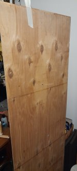
So I attached it to a 150cmx40cm x5mm which already has a hdn8 attached to it
I will compare these two at a later date.
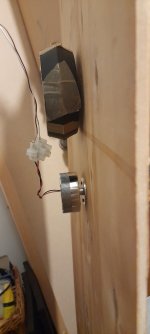
The holes for the screws are ridiculous small but luckily I found three screws that fitted even if they were a little too long.
I'm not happy with this mounting so will probably use a long bolt for future mounting.
Probably giving a 2inch gap between exciter and panel in an attempt to minimise the exciter and panel interference .
I also think in the second picture that something like a foam insert if used as is,might be a good idea to stop the metal spider from ringing 🤔.
To be tested.
I was surprised that this exciter sounds pretty bad on the smaller lighter panels that I have but sounds quite good on more heavy rigid panels and stud walls.
It drives them very well.
i have not seen this probem mentioned before ,if it is a problem?
this is my first experience with metal spiders.
The sound is not up to the standard of the ordinary exciters, but I think improvements can be made.
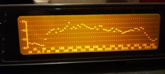
The frequency plot on the ply panel is not bad compared to others I have seen.
10k seems to be the maximum hf for this exciter so far.
On this panel it just about reaches down to 40hz.
The measurement was taken at about 60cm.
If anyone has had similar experiences with this exciter and has any good ideas to improve them ,please let me know.
I'm mainly looking at this exciter to use on walls or on a Small PA type panel so ultimate fidelity is not an issue.
Steve.
So I attached it to a 150cmx40cm x5mm which already has a hdn8 attached to it
I will compare these two at a later date.
The holes for the screws are ridiculous small but luckily I found three screws that fitted even if they were a little too long.
I'm not happy with this mounting so will probably use a long bolt for future mounting.
Probably giving a 2inch gap between exciter and panel in an attempt to minimise the exciter and panel interference .
I also think in the second picture that something like a foam insert if used as is,might be a good idea to stop the metal spider from ringing 🤔.
To be tested.
I was surprised that this exciter sounds pretty bad on the smaller lighter panels that I have but sounds quite good on more heavy rigid panels and stud walls.
It drives them very well.
i have not seen this probem mentioned before ,if it is a problem?
this is my first experience with metal spiders.
The sound is not up to the standard of the ordinary exciters, but I think improvements can be made.
The frequency plot on the ply panel is not bad compared to others I have seen.
10k seems to be the maximum hf for this exciter so far.
On this panel it just about reaches down to 40hz.
The measurement was taken at about 60cm.
If anyone has had similar experiences with this exciter and has any good ideas to improve them ,please let me know.
I'm mainly looking at this exciter to use on walls or on a Small PA type panel so ultimate fidelity is not an issue.
Steve.
Attachments
I have watched the video you posted here, as well as a few others later. Did you take the final readings/measurements in that room? It is cluttered with junk! How can you obtain accurate measurements in such an environment? As in this post?Steve.
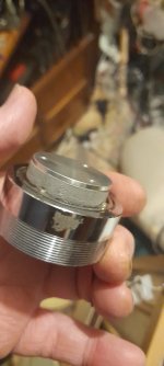
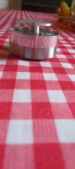
By the way, that Aiyima "exciter" is more of a party gadget than something intended for serious use. It is designed to be placed horizontally.
It is far too heavy to be suspended on any surface without proper support. The Aluminium plate ( shock rod) will transmit vibrations, but at the same time, it will cause the driver section to vibrate as well. This will also result in the shock rod becoming loose from the driver section; in other words, its screw will become undone.
Of course, you can turn it into a functioning exciter, but only if you discard that "shock rod" and use the blocked metal spiders to transfer vibrations directly to a flat panel. You would need to attach a very thin transfer plate to the flat centre of that spider. In any case, you must support the heavy driver section to prevent it from moving or vibrating along with the support. (It is quite difficult to dismantle the device; I attempted to do so some time ago.) By the way, it can turn the entire door into a speaker, and even the wall.
Aiyima even has a larger model.
Last edited:
"Now something completely different..."
Please forgive my english, first of all. This thread got my attention months ago. I used exciters for the first time some years ago while making a large (2 sq m) plate reverb and I still had one Monacor AR-30 spare, so I tried to arrange a mono DML panel just for the fun of trying.

My first attempt was with a 100x70x1 cm poliplat sheet, which is a foam core panel with paper glued on both sides, with rounded corners and 2/5 3/5 placement of the exciter, suspended. It sounded very loud but I got bored very soon as it lacked bass and it was screaming too much in the mids, so I tried with a different material.

Take 2 was made using a 100x70x0,3 back panel of an Ikea frame, I think it's like hot pressed sawdust. It sounded much quieter than the previous one and lacked high frequencies, but some kind of bass was there and the sound reproduction was more enjoyable to my hears.

I was ready to purchase some more exciters and make a "proper" pair of stereo speakers using 2 mm plywood panels for my attic, which is an open space floor with a 4x4m room in a corner, made using interlocked wood boards 2 cm thick. I wanted to suspend the DML panels on the outside of the room (that room is a closet, not a living space), when I realized I was mounting wood panels on a wood wall, which seemed kind of redundant to me. So I tried to stick the Monacor exciter directly to the wood wall, and it sounded much better than the previous attempts: loud, clear and with enough bass for my taste, good enough for listening to some music and podcasts while working.


I made tests mounting the exciter on both sides of the wall, as I loved the idea of concealing the exciters inside the closet, but the loss in treble was too much noticeable, so I decided to mount them in sight. I bought four DAEX32U-4, two in series for each channel, and after some empirical testing for finding the best positions I placed the exciters on the wall. The outside of the wood wall has some grooves in it and it's not perfectly smooth, so after finding the sweet spots I prepared the area using plaster first and sandpaper after. Two are placed in the upper part of the wall, two are in the lower part, below the window level and concealed by furniture.

For driving the 8 Ohm loads I'm using an old Pioneer amp from 1991 which outs 2x30W @8Ohm. I noticed from the beginning that I needed to apply some kind of EQ as the wall was very prone to resonate with specific bass frequencies. I first tried with the Pioneer onboard bass control but the filtering was obviously too coarse for my needs, so I put a 31 band EQ in the equation. I found out that the 63 Hz band is the baddest, but in some way I needed to lower everything below 100 Hz to make it sound decent. Now I like the result but probably I will add a small subwoofer in the future. As last, I added some hoods to the exciters, to make them less noticeable.

Now, speaking of the listening experience... I'm close to 50, I'm a musician, I run a live music club, in some way I've been into hifi and sound stuff since I was 15, but I'm still impressed by how this cheap 4x4m wall sounds. Very natural, very loud, very clear, and everywhere. The stereo separation is quite noticeable even if the exciters are mounted on the same surface, and the sound pressure is... very different from "regular" speakers. Human voice, acoustic instruments and orchestra sound more than decent to me, electronics and heavier music are still lacking something and sometimes still can get a little confused, mostly when deep bass frequencies are directly involved. Adding a subwoofer with adjustable crossover frequency will sure make things much better.
Sorry for the long post, and thanks for all the useful info!
Please forgive my english, first of all. This thread got my attention months ago. I used exciters for the first time some years ago while making a large (2 sq m) plate reverb and I still had one Monacor AR-30 spare, so I tried to arrange a mono DML panel just for the fun of trying.
My first attempt was with a 100x70x1 cm poliplat sheet, which is a foam core panel with paper glued on both sides, with rounded corners and 2/5 3/5 placement of the exciter, suspended. It sounded very loud but I got bored very soon as it lacked bass and it was screaming too much in the mids, so I tried with a different material.
Take 2 was made using a 100x70x0,3 back panel of an Ikea frame, I think it's like hot pressed sawdust. It sounded much quieter than the previous one and lacked high frequencies, but some kind of bass was there and the sound reproduction was more enjoyable to my hears.
I was ready to purchase some more exciters and make a "proper" pair of stereo speakers using 2 mm plywood panels for my attic, which is an open space floor with a 4x4m room in a corner, made using interlocked wood boards 2 cm thick. I wanted to suspend the DML panels on the outside of the room (that room is a closet, not a living space), when I realized I was mounting wood panels on a wood wall, which seemed kind of redundant to me. So I tried to stick the Monacor exciter directly to the wood wall, and it sounded much better than the previous attempts: loud, clear and with enough bass for my taste, good enough for listening to some music and podcasts while working.
I made tests mounting the exciter on both sides of the wall, as I loved the idea of concealing the exciters inside the closet, but the loss in treble was too much noticeable, so I decided to mount them in sight. I bought four DAEX32U-4, two in series for each channel, and after some empirical testing for finding the best positions I placed the exciters on the wall. The outside of the wood wall has some grooves in it and it's not perfectly smooth, so after finding the sweet spots I prepared the area using plaster first and sandpaper after. Two are placed in the upper part of the wall, two are in the lower part, below the window level and concealed by furniture.
For driving the 8 Ohm loads I'm using an old Pioneer amp from 1991 which outs 2x30W @8Ohm. I noticed from the beginning that I needed to apply some kind of EQ as the wall was very prone to resonate with specific bass frequencies. I first tried with the Pioneer onboard bass control but the filtering was obviously too coarse for my needs, so I put a 31 band EQ in the equation. I found out that the 63 Hz band is the baddest, but in some way I needed to lower everything below 100 Hz to make it sound decent. Now I like the result but probably I will add a small subwoofer in the future. As last, I added some hoods to the exciters, to make them less noticeable.
Now, speaking of the listening experience... I'm close to 50, I'm a musician, I run a live music club, in some way I've been into hifi and sound stuff since I was 15, but I'm still impressed by how this cheap 4x4m wall sounds. Very natural, very loud, very clear, and everywhere. The stereo separation is quite noticeable even if the exciters are mounted on the same surface, and the sound pressure is... very different from "regular" speakers. Human voice, acoustic instruments and orchestra sound more than decent to me, electronics and heavier music are still lacking something and sometimes still can get a little confused, mostly when deep bass frequencies are directly involved. Adding a subwoofer with adjustable crossover frequency will sure make things much better.
Sorry for the long post, and thanks for all the useful info!
- Home
- Loudspeakers
- Full Range
- A Study of DMLs as a Full Range Speaker