Thanks alot for that github Christian - it's helpful to see a summary of designs in one place instead of trying to search through this whole thread. And thank you for the thoughtful comments. I'm thinking now that I'll just go ahead and throw some panels together and see how it goes, and then I can experiment with mounting, EQ, etc. afterwards. Thanks again for your help!Hello Colin,
Have a look here Github DML page. The first document is a kind of history file. There is a table summarizing some canvas realizations. Extract :
View attachment 1158439
Not sure it was the result of deep design investigation but more obviously copies... Canvas for painting are also mainly easy to find in rectangular shape. The canvas being identical in both directions, a square shape is not a good idea leading to have modes with the same frequency.
My current choice is DAEX25-4FHE. It is 4 ohms. I would have preferred 8 Ohms not because of the amp but because of the cut off frequency due to the inductance with the voice coil inductance. I won't worry about the impedance viewed by the amplifier. About the legs, no experience. What we read here is they are generally cut.
As for the proportions, there are not so much variants of this design so few experience. In mine, it is rectangular. The variant is to be with real balsa. It works but the others are light plywood. In posts with Spedge, we understood what he thought to have bought balsa was in fact basswood... probably a good choice.
My dream also when I started to build DML... I am afraid there is no real hope on this way. The rear wave has the same energy as the front one so very difficult to absorb it. Depending of the damping material, some energy will be reflected and combined with the front. Easy to test. Let us know your results... just don't start with a permanent attach method!
Same, low deviation from the original one... The canvas is probably not working on exactly the same physics as DML (vibration in a membrane versus in a plate), the common point is modes; Being at the centre, the force coming from the canvas tension is balanced in a better way for the voice coil.
My experience in EQing is to low to understand really your question. DML are suitable for EQing as they are based on modes. Due to the possible dispersion between panels (material, tension, exciter placement) some individual EQ could make sense. As first step, I would build them and then test them with REW each being at the same location to evaluate the similarities or differences.
Christian
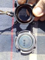
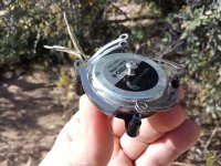
I got to thinking about this set of DAEX32Q-8 exciters that I screwed up and bought because I liked the out of the box design just to find they suck and thought I would try to salvage them.
I was going to carefully cut the rubber boot out of the equation but it dawned on me that since there was no spider the coil and leads should be contained in the plastic part and seperable from the magnet section without damage.
BOOM there it is! I took it all apart and instead of doing away with the rubber boot and using the lower metal spring set thinned down as was planned I just left all the springs as non contact and tested with the boot only.
Success... to an extent. The sound was good enough to where I replaced my rear surrounds with these to free up a pair of 24FHE's. I'll take it!
Attachments

Sorry Eucy,I did mean To get back to you, I did do tests using your dome method , but I was also doing other tests with whizzes and different domes.A shame about the dome non-test then Steve
So it all got a little confusing 🙄
I was using double sided tape to hold the dome on To the ply panel for quick removal, so probably not the best way of testing.
The db output was not as great as my other methods, but that could have been the tapes fault ?
But one thing I did notice which might be one of the things you were hearing,was the dome seemed to be covering up a lot of the central coil problems I have mentioned in the past.
I left it there as I have too many irons in the fire at the moment.
I can believe you when you say it improves the sound of your panels, but I personally have different ways of dealing with this area.
As with my methods it is very dependent on the panel material used, so if it works with your panel ,go for it.
Sorry I cannot be more conclusive, but hope this is enough ?
Steve.
That's fine Steve, feedback from others would be valuable and welcomed, but I'm convinced it works so that's enough in the end.Sorry I cannot be more conclusive, but hope this is enough ?
Steve
And yes, double sided tape would definitely kill the HF imo
Eucy
Christian.
as you asked.
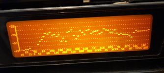
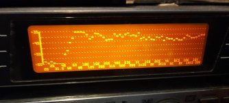
This was a quick measurement of the frequency response in the furthest away position from the exciter in the top left corner of the crate ply panel ,this was about 30cm
The second picture is the frequency response in the corner.
The third is the frequency response in the exciter area, which is the small dot of blu-tack near the middle of the panel.
as you can see the response in the primary coil area is a lot louder and has a fuller frequency response.
similar to a good full range driver.
the panel has a lower output than the primary drive area.
The HF holds up well in the corner up to 20k equal to the panels lower response.
Hope this is of some interest to you.
Steve
as you asked.
This was a quick measurement of the frequency response in the furthest away position from the exciter in the top left corner of the crate ply panel ,this was about 30cm
The second picture is the frequency response in the corner.
The third is the frequency response in the exciter area, which is the small dot of blu-tack near the middle of the panel.
as you can see the response in the primary coil area is a lot louder and has a fuller frequency response.
similar to a good full range driver.
the panel has a lower output than the primary drive area.
The HF holds up well in the corner up to 20k equal to the panels lower response.
Hope this is of some interest to you.
Steve
Attachments
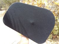
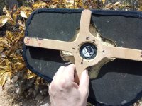
So after listening, a lot, to my wood/poly speakers I found them to be a tad too bright so I did what I did with my smaller center channel speaker and covered them with some really good speaker cloth, I think it's called.... mmmmm ...."old Haynes T shirt" ....yea that's it.
May be a sin to some but did exactly what I wanted and warmed these babies up just ever so slightly which I personally prefer. I didn't stretch it hard and left the buttons in place so the material is not actually lying on the panel. I sanded a pretty good concavity into these panels on initial build to start with. Sound great, very pleased! (super glue)
May be a sin to some but did exactly what I wanted and warmed these babies up just ever so slightly which I personally prefer. I didn't stretch it hard and left the buttons in place so the material is not actually lying on the panel. I sanded a pretty good concavity into these panels on initial build to start with. Sound great, very pleased! (super glue)
Attachments
Is there an overall consensus on fixing the exciter to a rigid surface or letting it vibrate along with the panel?
Consensus? Ha ha!
But seriously, there may actually be some consensus on this. Most people seem to agree that it’s better if the weight of the magnet is supported by something other than the spider. If not, then the magnet can start to sag and the voice coil be tilted off axis. Or worse the exciter might just fall off. However it’s not necessary that the support be rigid. It really just needs to support the weight of the exciter and keep it from sagging and not resonate itself. I use a spine attached rigidly to the frame and with a piece of foam between the back of the exciter and the spine to provide that support, but the foam layer is not necessary. And other people have found other ways to support the weight that work just fine too it seems.
But for quick tests, you can do that without a spine or any other support.
Eric
Last edited:
I think it might depend a bit on the exciter. I haven't tried smaller "coin" exciters, but suspect they might be fine. My DAEX30HESF-4 was fine unsupported initially, but they started to sag with extreme heat as well as over time, at least with intense usage. And when it sags it will cause clear distortion, making sine waves into square.Is there an overall consensus on fixing the exciter to a rigid surface or letting it vibrate along with the panel?
Surprisingly, even unsupported the exciters doesn't look like they vibrate even when pushing them very hard and panel is wobbling like crazy, so it doesn't seem to be needed to make the exciter work well in general. I just tied them up with strings to avoid the issue until I had built proper supports.
Isn't that logical and wouldn't the frequency response from a listening distance be more important?as you can see the response in the primary coil area is a lot louder and has a fuller frequency response.
similar to a good full range driver.
That unusually thorough Phd thesis I posted appears to have chosen multiple exciter spacing on the basis of the area where the exciter has most effect.
LOL In need of a life I have just bought a PC DML speaker setup. Something to play with and get my feet wet. It uses a subwoofer. They claim 70 to 250hz out of that and 200 to 18khz out of the DML's, panel size 200 x140mm. Material appears to be of the same type you showed edge on in your recently posted video that produced a rather nice tone. That from some one else's strip down of one. 🙂 |Actually I bought 2 sets as dismantling is a bit destructive and they may be of use. Little lost if crap.
Yes!...Exactly what I find...I use a damped zip tie as a form of hanger support from the panel, (photos posted way back somewhere), so the exciter mass is coupled to the panel and damped by the spider. Admittedly, my exciters are on the heavy end of the scale, but I can't see or feel the exciter body moving under normal listening conditions.Surprisingly, even unsupported the exciters doesn't look like they vibrate even when pushing them very hard and panel is wobbling like crazy, so it doesn't seem to be needed to make the exciter work well in general.
AjohnL,That unusually thorough Phd thesis I posted appears to have chosen multiple exciter spacing on the basis of the area where the exciter has most effect.
If you are referring to the thesis I think you mean, Leob correctly pointed out that what they are doing in WFS is different from what we are doing (stereo).

This is not to say that we can't learn some things from that thesis (I think we can), but just have to recognize the differences. Typical WFS uses a series of equally spaced speakers arranged all around the perimeter of the room, and each speaker gets a different signal. In the DML version of DFS, they use a bunch of wide DML panels, each with multiple exciters, all equally spaced across the width of the panel. As I understand it, this positioning of the exciters in such an equally spaced array is driven by the specific requirments for good synthesis of the wavefront, and actually despite the fact that some exciters (especially those near panel edges) are poorly positioned from a pure DML perspective. The ability to drive each exciter separately allows them to compensate for this I believe.
BTW, these WFS systems are really cool. My daughter worked in the Live Lab at McMaster Univ. in Ontario where they have auditorium with such a system (though not DML based, sadly). She took us on a tour of the Lab and the demonstrations were amazing. The one I recall most clearly was a demonstration where they made it sound like a bee was circling your head. You couldn't hep but try to swat it away!
Eric
Two main reasons to use a spine to support the exciter.
1. Most obvious is voice coil sag.
2. Is to prevent the magnet from (rocking) moving.
Without support both the voice coil as well as the exciters magnet move back and forth. In a conventional cone driver the only thing moving is the voice coil since the magnet is supported/stabilized by the basket frame. If there is no support at higher excursions the magnet will start to rattle due to the rocking inertia in which it can damage the voice coil.
Most say they cant see the exciters magnet moving? Play this track.
Warning , its not my fault if your exciters burn out due to this track🙂😉
Last edited:
Me to. That's all I meant by the comment I made when someones said it's just about WFS and not relevant to DML's as discussed in this thread, I think some construction aspects may be,This is not to say that we can't learn some things from that thesis (I think we can)
With the exciters I use I normally find that about 20 to 50 Hz signal will make the exciters really bounce, between 50 and 200 Hz they buzz to the touch, and above 200 Hz I can’t feel anything anymore. That track has some signal under 50 Hz!Two main reasons to use a spine to support the exciter.
1. Most obvious is voice coil sag.
2. Is to prevent the magnet from (rocking) moving.
Without support both the voice coil as well as the exciters magnet move back and forth. In a conventional cone driver the only thing moving is the voice coil since the magnet is supported/stabilized by the basket frame. If there is no support at higher excursions the magnet will start to rattle due to the rocking inertia in which it can damage the voice coil.
Most say they cant see the exciters magnet moving? Play this track.
Warning , its not my fault if your exciters burn out due to this track🙂😉
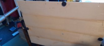
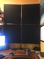
These are about done. In the first pic the panels are hanging on the wall by screws; out of the way. Fine for low volume while I'm working or something and can endure the problems at 500hz 🙂. Second pic they are "deployed" on the desk. At the top they are attached to the wall like hanging a picture but with enough play to lean forward; I can extend the string and adjust the legs to move them further in or increase the angle.
They can easily be removed from their spots in the corner and set up elsewhere in the room; mounted by wood clamps, for the best listening.
very happy with them -- for now.
wife even likes them; asked if I was going to add a third to the top. probably not for now, but I'd love to build some humongous ones for the house,
Attachments

Yep the lower the frequency the more pistonic they become and it usually starts at 100hz but you dont really see it moving untill 50hz and below.With the exciters I use I normally find that about 20 to 50 Hz signal will make the exciters really bounce, between 50 and 200 Hz they buzz to the touch, and above 200 Hz I can’t feel anything anymore. That track has some signal under 50 Hz!
Although that bass track I posted is an extreme example there are many audiophile music that have bass 50hz and below.
@Lawnboy , @Audiofrenzy , @LeobWith the exciters I use I normally find that about 20 to 50 Hz signal will make the exciters really bounce, between 50 and 200 Hz they buzz to the touch, and above 200 Hz I can’t feel anything anymore. That track has some signal under 50 Hz!
Spine or not ? Question in #9828
Answers : 9829, 9830, 9834
Bass test tracks : 9834, 9838
I am convinced too
Starting from the list in the previous posts :
1. Most obvious is voice coil sag.
2. Is to prevent the magnet from (rocking) moving.
3. Is to limit the risk of unstuck exciter by removing the exciter weight effect from the voice coil/membrane bonding
4. From 1. and 2. : distortion reduction and better power handling and at the end a better reliability might be expected.
5. The spine/support has to be designed to avoid any additional constraint on the exciter and a minimum of acoustic mask for the rear wave (read below)
My experience :
- I don't know if the distortion reduction can be heard but 1st measurements shown it.
- I build a canvas pair more than one year ago and I still have them working with a TV set, I can confirm after a time the sag effect (the magnet axis was no more aligned on the voice coil axis). I added a spine. My plywood panels that have been working also now for more than one year have also one from the beginning...
- For my plywood panel, the design is correct from the mechanical point of view but can be improved for the overall performance has its surface is too important. Blocking the air in the voice coil area by its relatively important surface, it creates a kind of horn (peak at 2kHz).
- short term for testing : possible without spine/support
- long term, "final design" : with
Christian
I should have clarified that my comments about support is based on using the plates with an HPF. For sub frequencies I don't doubt that an unsupported exciter can start moving and cause issues also without sag.
The discussion was about if multiple exciters on the same plate interfere with each other, and I merely pointed out that it is a big difference if you have spread out exciters with different signals to each exciter, or if you have a cluster with exciters playing the same signal. Both are DML applications, but with some different considerations. If you don't see that difference I really doubt you can get much out of reading those papers.Me to. That's all I meant by the comment I made when someones said it's just about WFS and not relevant to DML's as discussed in this thread, I think some construction aspects may be,
- Home
- Loudspeakers
- Full Range
- A Study of DMLs as a Full Range Speaker