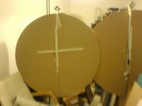
I saw how you made the new Walsh speaker in YT. Have you made a video on this too? How about making a larger round panel with the same idea? It is still a DM panel, even though they won't say it. Looks like they don't want any NXT sounding terminology. 🙂I have made some prototypes along these lines i.e. BMR. I have used a regular 7 inch foam surround in both cases. The diaphragm is 2mm balsa an CF. The black one is 3D printed as you can see. It uses the tectonic driver as I have used in previous speaker. The box is a reversed exponential horn , similar to B&W nautilus.
The other is using a sallads bowl from ikea🤪 and an exciter from dayton (It is closed box).
View attachment 1131709View attachment 1131710View attachment 1131711View attachment 1131718
Nope no video.I saw how you made the new Walsh speaker in YT. Have you made a video on this too? How about making a larger round panel with the same idea? It is still a DM panel, even though they won't say it. Looks like they don't want any NXT sounding terminology. 🙂
Yes, I made one 15 inch with the dayton exciter. I scraped it. Maybe too early…Now, I think it was severly underpowered…


I'm surprised it was underpowered with that small area .. I use these exciters and they pack a punch! Perhaps it's more likely a matter of trying to mimic a BMR with an exciter which has inherently low excursion and needs a larger panel area to generate sufficient output from bending waves.Nope no video.
Yes, I made one 15 inch with the dayton exciter. I scraped it. Maybe too early…Now, I think it was severly underpowered…
View attachment 1131734View attachment 1131735
Eucy
Here you go Christian. I thought after I sent this originally it probably didn't show what you were looking for.Thank you Dave. Is it possible you focus on let say -10 to 30ms to show the decay of the resonances. Sorry not having specifying it before.
Christian
Thanks, Dave
Attachments
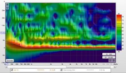
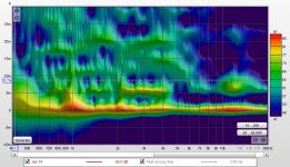
Dave,Here you go Christian. I thought after I sent this originally it probably didn't show what you were looking for.
Thanks, Dave
Thanks for sharing those. The thing I find most remarkable is that I don't see any evidence of "ringing" at the panel's natural frequencies, in either spectrogram. I kind of expected that perhaps the "before EQ" might show more ringing than the "after EQ". But I don't see clear evidence of ringing in either spectro. What I mean by "evidence of ringing" is what I showed here:
https://www.diyaudio.com/community/...ing-of-dml-speaker-panels.394465/post-7234486
in my first two spectrograms, where the damping was apparently poor, there are vertical lines in the spectrograms, corresponding to frequencies that "ring" long after the signal is gone. Only the third one, with a well damped perimeter, approaches either of you spectrograms.
Can you tell me what is the foam you have around the perimeter? I would not have guessed that a strip of foam around the edge (but not attached to a frame) would be as effective as your foam appears to be. Did you ever do a measurement before adding the foam? If so I'd be really interested to see that too!
I guess another possibility is that your core (nomex, right?) has good damping properties. But I never recall hearing that about nomex before.
I also don't quite understand exactly how the panel is mounted. I know it's a "temporary mount" but still I'm curious exactly what you've done there.
Thanks
Eric
More you read NXT patents, more you find them as somewhat pseudo-science. First thing that hit me was while the waves travel away radially, why should a round exciter with a round coil former should run a rectangular panel and that too from an asymmetric place. That way, while some of the waves gets cut at the edges at different times, some are still travelling to longer edges, even though the time difference is tiny. It doesn't match with common sense.
It so appears that all NXT did was to create patents, rather than products. Just to sell the patents and licenses. And, finally it went bust. NXT turned into HiWave Technologies, which too went bust. Both NXT and HiWave Tech existed somewhat simultaneusly, though. Henry Azima resigned from both companies in 2007 and no one practically heard of him after. HiWave got into financial troubles in 2013 and was placed on administration, then was divided into at least two parts, one of which was bought by FLAT Audio Technologies, LLC in 2013. It was NXT or HiWave Tech, by the way, patented BMR technology first, and they even made rectangular BMR speakers.
Later, Tectonic patented an 'improved' Audio transducer stabilization system and method, which Leob has used to successfully make his DML PA system. Here, the transducers are in the middle, and maybe they kept the rectangular shape for easy sourcing and producing reasons. Looking at their patent, they could've made it simply round, but then, anyone can place a transducer in the middle. Best make the idea hard to fathom. 🙂 Distributed mode becomes (distributed) balanced mode...
Last edited:
Here's simulations on baffles, not panels. But the principles are probably similar.
1. Simulated baffle response for a round baffle, 600mm dia, with driver in the middle, note the comb effect of around 30dB:
2. Simulated baffle response for a rectangular baffle 500x700mm with driver off-centre. The baffle introduces only 5dB of interference.
This might explain why one hardly ever sees round baffles UNLESS they have been carefully chamfered and bevelled to eliminate edge effects.
Here's simulations on baffles, not panels. But the principles are probably similar.
1. Simulated baffle response for a round baffle, 600mm dia, with driver in the middle, note the comb effect of around 30dB:
View attachment 1131933View attachment 1131931
2. Simulated baffle response for a rectangular baffle 500x700mm with driver off-centre. The baffle introduces only 5dB of interference.
View attachment 1131934View attachment 1131932
This might explain why one hardly ever sees round baffles UNLESS they have been carefully chamfered and bevelled to eliminate edge effects.
I have a pair. Doing very well, though quite old. No 'baffles' as such. Round around the speakers, the two side sunk tweeters also are somewhat round around them, only hidden out of the way, looking away at about 45 degrees. If you look at most of the Japanese, Korean speakers, most of them have jutting out 'baffle' rounded around the speakers.
Last edited:
Andre.
And what would the response be if you off set the exciter on the round panel ?I
Steve.
And what would the response be if you off set the exciter on the round panel ?I
Steve.
A much, much better response, because the distances from the driver to the edges are all different. An ellipse or a pentagon is probably the best shape for a baffle.Andre.
And what would the response be if you off set the exciter on the round panel ?I
Steve.
I'm not saying that mass-produced plastic speaker casings are not fine examples of sound design, but even in a cheap speaker like that, it's all "... carefully chamfered and bevelled to eliminate edge effects...."View attachment 1131941
I have a pair. Doing very well, though quite old. No 'baffles' as such. Round around the speakers, the two side sunk tweeters also are somewhat round around them, only hidden out of the way, looking away at about 45 degrees. If you look at most of the Japanese, Korean speakers, most of them have jutting out 'baffle' rounded around the speakers.
Andre
I was hoping you might show ,using your simulation, the ideal placement for an exciter on a circular panel.
You can only move the exciter only one way so it should be easy to find ?
Steve.
I was hoping you might show ,using your simulation, the ideal placement for an exciter on a circular panel.
You can only move the exciter only one way so it should be easy to find ?
Steve.
It is not the question of "cheap", "mass produced", "plastic" etc, but the companies that produce such speakers have massive R&D departments. You might've noticed that the whole speaker is jutting out in a round encloser/tube that has nothing to do with the chamfering below it.I'm not saying that mass-produced plastic speaker casings are not fine examples of sound design, but even in a cheap speaker like that, it's all "... carefully chamfered and bevelled to eliminate edge effects...."
Have a look at this,
The whole speaker juts out in a tube and has no connection with the curved 'baffle' below it. And, the tweeter is in a horn.
I have these too. These speakers, when placed flat next to the wall have so-called wide sweet spot at least 1.5m away from their plane, that you can walk around the room and the music follows you. LG too has massive R&D department. I have few other LG speaker pairs. 🙂
LG has massive R&D departments? They make cheesy mini systems, they are not hi fidelity companies like Kef, Focal, B&W, just to name a few.It is not the question of "cheap", "mass produced", "plastic" etc, but the companies that produce such speakers have massive R&D departments. You might've noticed that the whole speaker is jutting out in a round encloser/tube that has nothing to do with the chamfering below it.
Have a look at this,
View attachment 1131944
The whole speaker juts out in a tube and has no connection with the curved 'baffle' below it. And, the tweeter is in a horn.
I have these too. These speakers, when placed flat next to the wall have so-called wide sweet spot at least 1.5m away from their plane, that you can walk around the room and the music follows you. LG too has massive R&D department. I have few other LG speaker pairs. 🙂
Thank you DaveHere you go Christian. I thought after I sent this originally it probably didn't show what you were looking for.
Thanks, Dave
I see Eric has already ask for the questions I have too! No evidence of modes. Interesting. The damping by the material, how it modifies the measurements, how it changes the feeling with music is an almost open topic, the use of the spectrogram and the time behavior too.
Christian
First , you have to have hi-fidelity ears... 🙂LG has massive R&D departments? They make cheesy mini systems, they are not hi fidelity companies like Kef, Focal, B&W, just to name a few.
LG R&D centre.
Kef, by the way, is owned by the Chinese. Wharfedale too.
Last edited:
The idea is to (under) suspend the perimeter...Some of my earliest panels were large round cc panels.
I used to offset the exciter for a better sound using my hearing only.
Steve.
André,A much, much better response, because the distances from the driver to the edges are all different. An ellipse or a pentagon is probably the best shape for a baffle.
I don't think the model used for an open baffle works for a DML. In a DML, there are sound emissions on all the surface, the emitting point changing with the frequency according to the mode shape (in a frequency representation meaning in a steady state with a sinus input). In some papers, the DML are said "self baffled" to say the membrane and the baffle are the same object. I point that because more than one year ago I made a comparison between a canvas panel (ok this is probably not exactly a DML) and a small full range on a same dimension open baffle). the FR in the low freq (below let say 500Hz) are completely different. No bass from the OB, bass from the canvas. Some 2D or 3D simulations of the front and rear wave propagation and recombination should help.
Christian
- Home
- Loudspeakers
- Full Range
- A Study of DMLs as a Full Range Speaker