Too many things strange in those videos... It would be more interesting to see explicitly the REW settings than how to drill or to screw...this is also interesting if you are interested in bracing ,clear panels , and all in one sub and panel speakers.
he does not seem to worry about the rising treble though ?
he has made quite a few videos of his panel projects.
steve.
Among the strange things :
- the FR are from 200Hz to 20k. Even if not use a view below 200Hz is informative at least about the 1st resonance
- the way to smooth the FR : 1/12th oct smoothing why not but smoothing with a 1ms fixe time window sounds like a mistake if the goal is to get the FR. It might be a way to get a mean value but for sure it doesn't remove the reflections, it simply remove the information and let only the 1k, 2k... points
- in the waterfall, the rising HF seems disappearing? no?
- I don't really know how to use the waterfall but after a quick test I see we can adjust the floor as we want. So how to define a decay time test without defining a level drop?
I have perhaps watched too quickly this video
Let see what will come next.
Sorry Toddincabo : I missed the epoxy step...The left over cone acted as a cup that I filled with epoxy achieving the same thing as in your picture. I just don't see a homemade coming close to a true exciter in any fashion, you will always be leaving a lot off the table.
You can buy 8 Ohm exciters all the way down to 5w.
Could you be more precise about the second part of your reply? Which characteristics do you think not reachable from a modified speaker? I have neither made a test or even think more deeply to it...
About the 8 ohms exciters, I will have a look on the availability but I have in mind the offer is not so large.
This is the next video which still shows the skyrocketing HF ?I asked him that very question back when he released that video (subscribed) and he replied that coming up next was a crossover to hopefully take care of that skyrocket high end.
I know this material to have a very bright harsh sound.
Steve.
Last edited:
Once I received my 25w Dayton exciters and did a side by side test with the higher watt homemade "exciters" it was just not even close. I used 14 x 15" eps panels 3/4" thick and you couldn't even hear the homemade because the true exciter drowned it out at any volume level. I went A B so I could turn them up and down quickly and the quality just wasn't there with the homemade as well, top to bottom, to me anyway. You could possibly hit a magic scenario and be satisfied, but I've given up myself.Sorry Toddincabo : I missed the epoxy step...
Could you be more precise about the second part of your reply? Which characteristics do you think not reachable from a modified speaker? I have neither made a test or even think more deeply to it...
About the 8 ohms exciters, I will have a look on the availability but I have in mind the offer is not so large.
Check out this page for 8 Ohm, there's a bunch of em'.......
https://www.parts-express.com/search?order=relevance:desc&keywords=8 ohm exciter
Last edited:
My Bad, I did watch that crossover video and yea, I don't see that highest end getting close to flat along with the rest using acrylic. He seems to be content so that's the main thing. I reckon we'll see if it gets tweaked any further. I personally couldn't listen to those for long.This is the next video which still shows the skyrocketing HF ?
I know this material to have a very bright harsh sound.
Steve.
Last edited:
Hi ToddOnce I received my 25w Dayton exciters and did a side by side test with the higher watt homemade "exciters" it was just not even close. I used 14 x 15" eps panels 3/4" thick and you couldn't even hear the homemade because the true exciter drowned it out at any volume level. I went A B so I could turn them up and down quickly and the quality just wasn't there with the homemade as well, top to bottom, to me anyway. You could possibly hit a magic scenario and be satisfied, but I've given up myself.
Check out this page for 8 Ohm, there's a bunch of em'.......
https://www.parts-express.com/search?order=relevance:desc&keywords=8 ohm exciter
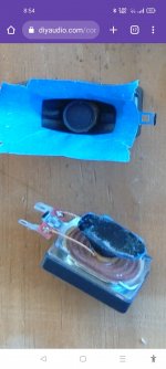
Was the high diy one 14w as shown in the photo?
No disrespect intended, but those two speakers don't look "exciting" (pardon the pun).
Eucy
YesHello Toddincabo
+ @Eucyblues99
The idea to make exciter with a speaker is interesting. It could be a way to get higher force factor (BL) and maybe lower inductance in a 8 ohm impedance... which I think a way to get better HF.
Yes..I think a plastic cylindrical former with a flange for mounting is requiredFrom your pictures Toddincabo (#3076), I see the membrane was may be not completely removed so that the voice coil pushes the membrane through a flexible remaining part of cone.
See below how I dismount a speaker for an application close to that (at this time i didn't know the DML). I think I glued a disk (which material?) on top of the voice coil). With care, a small cylinder might be added.
I think there are 2 difficulties at least:
- the voice coil end is close to the spider. Some very rigid interface part might be needed
3d printing ?
Hmm... you're correct, my exciters allow some wiggle...how do they do that? Big voice coil gap? That would adversely affect flux..
- an exciter is designed to accept an angle between the voice coil axis and the magnetic circuit, a speaker not. So it needs more precise position.
YepAnd of course a spine.
Yep againSo not easy... but why not.
I'd try with a reasonable quality speaker to get a decent foundation.
Worth at least one try
I think 20w was the highest I tried. They came out of some Sony powered desktop speakers that the electronics went bad. Oh, I agree, nothing exciting looking about those homemades.Hi Todd
Was the high diy one 14w as shown in the photo?
No disrespect intended, but those two speakers don't look "exciting" (pardon the pun).
Eucy
I imagine a big slug of epoxy in the cone remnant would muck up the response somewhat...I think 20w was the highest I tried. They came out of some Sony powered desktop speakers that the electronics went bad. Oh, I agree, nothing exciting looking about those homemades.
On your post 5270, what were your conclusions from the roll off applied ?Hello Steve,
Have a look on post #5270 for tests and comment.
To be more clear, I made a quick simulation on LTspice.
Here is the schematics that models the circuit of the test above:
View attachment 1073259
R1 is one exciter with a capacitor C1 across its connections
R2 is the second exciter
Below V(Exc1) is the voltage (so the level) across R1, V(Exc2) the voltage across R2. I show also the sum which is constant.
View attachment 1073262
Sorry for the dark background. I didn't find how to change it
The impedance for the amplifier is not constant : 8 Ohms to fall to 4 Ohms (not shown here)
The R2 (Exc2) will work full tension in HF.
As the power is mainly in the low to mid frequency, the power handling might be improve also.
Christian
There does not seem a lot of difference , except for a slight increase between 3k and 6k ?
Not to mention the dip below 100hz ?
Steve.
The panel is smaller and thinner than the other panels he has used in his other previous videos .Too many things strange in those videos... It would be more interesting to see explicitly the REW settings than how to drill or to screw...
Among the strange things :
So the measurement side seems not ok.
- the FR are from 200Hz to 20k. Even if not use a view below 200Hz is informative at least about the 1st resonance
- the way to smooth the FR : 1/12th oct smoothing why not but smoothing with a 1ms fixe time window sounds like a mistake if the goal is to get the FR. It might be a way to get a mean value but for sure it doesn't remove the reflections, it simply remove the information and let only the 1k, 2k... points
- in the waterfall, the rising HF seems disappearing? no?
- I don't really know how to use the waterfall but after a quick test I see we can adjust the floor as we want. So how to define a decay time test without defining a level drop?
I have perhaps watched too quickly this video
Let see what will come next.
So he is not intended in frequencies below the 250hz XO point he is using.
he also mentions he is on a leaning curve with the measuring software in previous videos.
similar to his understanding of passive XO circuits.
Steve.
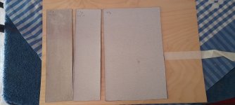
I made another panel exactly the same as the egg whites panel but using PVA throughout.
I also made some test strips of single .5mm to test increased weight and stiffness.
I coated one strip in egg whites and the other PVA.
The strips weighed 13g , when wet they increased to 14g each .
When dry again they each reverted back to 13g.
The two .5mm larger test panels weighed 57g before gluing and coating.
I coated both sides in neat PVA before sticking together .
When dry I coated the outside of the panel in 50x50 PVA and water.
The weight increased to 60g and when dry is now somewhere between 58g and 59g , my scales aren't that accurate.
So some useful stiffening with very little weight 😉
As I am typing this I was going to say the egg whites seem to stiffen the card more, but the egg whites card seems bulkier ?
So I just tested the thickness, and the .5mm egg whites strip does feel tighter in the gauge ?
So the egg whites does seem to be expanding the fibres and drying in that state.
Similar to expanding the grain on wooden instruments before sanding ?
But the PVA mix either shinks back or stays the same when dry ?
But which sounds the best ?
Steve.
Attachments

I wanted the clearest possible voices when watching movies so.... boom... a couple of simple center speakers (above and below screen). Made out of my mystery material (spray foam consistency). They sound great after adding the thin, stretchy material which took care of the super highs. I test my highs with Simply Red's - Holding Back The Years. When I can get my panels right below his highs not piercing my ears while being clear and smooth , that's what I'm comfortable with.
You can see in the photos how I sculpted the material front and rear. I drilled and tapped the existing holes in the exciter frame which the 2 mounting bolts simply screw into through the wood block, all four not being necessary. I also super glued a small amount of foam on each corner just to help with any future sag (personal choice).
These are the cleanest and easiest DML's I've made yet. I run these and FL and FR set as small in my receiver which sets bottom end at 110hz letting the subs do their thing up to 120.
These would be perfect candidates for atmos ceiling speakers. These can be mounted up, down, all around as long as you have the corner foam pieces glued good.
Last edited:
SteveOn your post 5270, what were your conclusions from the roll off applied ?
There does not seem a lot of difference , except for a slight increase between 3k and 6k ?
Not to mention the dip below 100hz ?
Steve.
I wouldn't speak of roll off with this circuit (but i might be wrong in the meaning of roll off). The goal of the circuit is to keep the sum of the exciters output constant. In low frequency, both receive half of the signal, in high frequency, one is "short circuited" by the capacitor, the second receive the full signal so twice the signal at low frequency. 2 sources in low frequency, only one in high frequency. A bit schematic but it is the idea.
The measurements on both graph are:
- red : only one exciter on the panel
- purple/blue : is 2 exciters and the capacitor
- other curves are 2 exciters without capacitors in different positions on the panel
The conclusion is the 2 exciters plus capacitor configuration is the one that is the closest of the one exciter.
So if I come in the future to a 2 exciters configuration, I will give a try to the capacitor configuration
About the 100Hz, it was out the scope of the test. It is just a piece of XPS 9mm not really large.
Christian
Hmm. Not easy to judge like that... Each part has a stiffness and a mass; relevant or not in the range of frequencies considered. The cone acts like a spring between the coil and the panel. I did some test with additional parts between the exciter and a membram. Even if my perception of the part was "stiff", I lost something in the high frequencies; For the mass, I made test also; It is always incredible for me what we can add without changing a lot the FR. It has some influence on the time where the peak of amplitude is for mid frequencies (sort of resonance).I imagine a big slug of epoxy in the cone remnant would muck up the response somewhat...
A table or some comparator might help : high BL, low inductance, if possible 8 ohms, power handling if possible around 20W, 10W minimum... what is remaining?Once I received my 25w Dayton exciters and did a side by side test with the higher watt homemade "exciters" it was just not even close. I used 14 x 15" eps panels 3/4" thick and you couldn't even hear the homemade because the true exciter drowned it out at any volume level. I went A B so I could turn them up and down quickly and the quality just wasn't there with the homemade as well, top to bottom, to me anyway. You could possibly hit a magic scenario and be satisfied, but I've given up myself.
Check out this page for 8 Ohm, there's a bunch of em'.......
https://www.parts-express.com/search?order=relevance:desc&keywords=8 ohm exciter
Christian
Hmm..my turn to Hmm...😀Hmm. Not easy to judge like that... Each part has a stiffness and a mass; relevant or not in the range of frequencies considered. The cone acts like a spring between the coil and the panel. I did some test with additional parts between the exciter and a membram. Even if my perception of the part was "stiff", I lost something in the high frequencies; For the mass, I made test also; It is always incredible for me what we can add without changing a lot the FR. It has some influence on the time where the peak of amplitude is for mid frequencies (sort of resonance).
I understood the 'funnel' was filled with epoxy? If so, then there's no spring effect and the added mass to the voice coil is significant and surely must affect acceleration / deceleration and hence at least hf response. (Epoxy SG is 1.1)
Similar to adding a number of washers to the panel at the centre of the coil.
The other effect is to significantly widen the contact area on the panel which further affects hf response.
Eucy
Did you do a test of the two exciters , in the same positions , but one with the capacitor and one without?Steve
I wouldn't speak of roll off with this circuit (but i might be wrong in the meaning of roll off). The goal of the circuit is to keep the sum of the exciters output constant. In low frequency, both receive half of the signal, in high frequency, one is "short circuited" by the capacitor, the second receive the full signal so twice the signal at low frequency. 2 sources in low frequency, only one in high frequency. A bit schematic but it is the idea.
The measurements on both graph are:
The difference between the 2 graphs is in the second one a time dependent window is used so only the level at beginning of the pulse.
- red : only one exciter on the panel
- purple/blue : is 2 exciters and the capacitor
- other curves are 2 exciters without capacitors in different positions on the panel
The conclusion is the 2 exciters plus capacitor configuration is the one that is the closest of the one exciter.
So if I come in the future to a 2 exciters configuration, I will give a try to the capacitor configuration
About the 100Hz, it was out the scope of the test. It is just a piece of XPS 9mm not really large.
Christian
The best way to see the combing effect is by moving the microphone between the two exciters and watching the wave move up and down the frequency scales.
With DML It is very difficult to make assumptions about single point measurements if they are not made in exactly the same condition and positions.
Moving the microphone a few cm can change the response plot from very good to not so good or bad .
This is why I prefer to wave the microphone around my room seating area to get a good average of the response, in that area.
Steve.
I don't know if this is off topic, but i find this article an interesting reading. It deals with the the issue of chasing the ideal/neutral sound as a utopian endeavour and touches few nerves when discussing the relation between the ears and the brain.
https://diyaudioheaven.wordpress.com/tutorials/neutral-sound-an-utopia/
https://diyaudioheaven.wordpress.com/tutorials/neutral-sound-an-utopia/
- Home
- Loudspeakers
- Full Range
- A Study of DMLs as a Full Range Speaker