@VelericEric:
I tried other angles too, just mentioned 90 degrees for brevity. I guess you would see coincidence if you had a directional mic, and averaged 3 readings at a distance just clear of the panel, moving the mic above and below centre in a circle around the panel centre whilst maintaining the angle from the normal. Then repeat at several frequencies, you should see a peak moving.
On response regions/regimes. Yes would be wonderful to have such tools but expense is prohibitive.
It looks like I have assumed at some point that coincidence was indeed at lower f than it really is, even for non-exotic materials. I read that Zenker paper (and thought it was a good one), looks like the penny didn't drop, guess I assumed his material choice put fc up high. I remember reading fc values for aluminium panel at several thousand Hz, and had assumed for foam/ply it would be much lower. Plus, some papers stress how, below coincidence, radiation is very inefficient with only edge and corner modes, and I made the connection to the low frequency rolloff. If fc is typically much higher, looks like panels get along with edge modes just fine! If that is the case, then fc may be of much less consequence for practical designs in foam or ply.
Just to make a quick feedback : I made tests at different angles from 60° to 90°. Nothing obvious to find a coincidence frequency. Just again the proof of the almost absence of directivity.
Christian
Sebastion.
I don't know how it would relate to you bracing ?
But when I was using my stud wall as a panel speaker , I found the sound was much fuller when the exciter was on the wooden stud, than when it was inbetween on the plaster board.
I did , I believe make a recording of this , somewhere on this forum.
Steve.
Sebestian.
actually the video of the guitar building, talks of the bridge as the main drive for the guitar.
Steve.
actually the video of the guitar building, talks of the bridge as the main drive for the guitar.
Steve.
Sorry if I missed it but I'm surprised no one has noted the similarity between Sebastian's panel and the JMC soundboard.
Click the "presentation" link here for more images.
http://www.jmclutherie.com/en/soundboards/jmc-soundboard-loudspeaker-built-musical-instrument
main site
http://www.jmclutherie.com/en/Soundboards
Curiously (to me, anyway) JMC seems to sell this as a single speaker, rather tan a stereo pair.
Eric


Click the "presentation" link here for more images.
http://www.jmclutherie.com/en/soundboards/jmc-soundboard-loudspeaker-built-musical-instrument
main site
http://www.jmclutherie.com/en/Soundboards
Curiously (to me, anyway) JMC seems to sell this as a single speaker, rather tan a stereo pair.
Eric

And the award for most complicated dml build goes to JMC !!!!
I hate to think how much this panel would cost.
I might be cheaper to put and exciter on my wife's piano ?
let's not forget that this is designed to go flat on the wall.
So it is not omnidirectional.
Steve.
I hate to think how much this panel would cost.
I might be cheaper to put and exciter on my wife's piano ?
let's not forget that this is designed to go flat on the wall.
So it is not omnidirectional.
Steve.
We are doing a renovation right now and I just mixed Polyurethane and mineralSPIRITS!!! NOT oil, that we had for cleaning stuff. I am so sorry, I mis"wrote".This thread is an excellent possibility to learn about many think! Odie's oil... Never heard about before... I had a look at their site. One picture reminds me the color of the wood floor at cousin's in Canada (Québec) I found so nice.
Polyurethane and mineral oil : is it a diluted polyurethane varnish?
I applied a diluted varnish (no sure it was polyurethane) on my plywood panel. On one side first... bad idea not doing the both side the same time because it then warps but after gluing with the full peripheral foam (17x17mm) no problem. The membrane has been still perfectly flat since.
Christian
I tried to make both application super thin, so that they would not affect things too much, but some protection from moisture it had to be. Instruments are usually protected with shellac and that is ultra thin, too. On the back side this is so thin that the wood fibers can still be felt.
Sebastian
Hello Valeric,Sorry if I missed it but I'm surprised no one has noted the similarity between Sebastian's panel and the JMC soundboard.
Click the "presentation" link here for more images.
http://www.jmclutherie.com/en/soundboards/jmc-soundboard-loudspeaker-built-musical-instrument
main site
http://www.jmclutherie.com/en/Soundboards
Curiously (to me, anyway) JMC seems to sell this as a single speaker, rather tan a stereo pair.
Eric
View attachment 1042846 View attachment 1042845
that is super interesting and make me even more confident that I am on the right path :-D
I wonder if they enforced the curve to have more tension/stability in the board. And it looks like they did not really dampen their board. I wish I could do that, too. Did they actually identify these 4 mounting spots to be the least moving spots?
What surpises me is that the bracing is parallel and I would have thought that this might introduce resonances,... but maybe I was wrong.
Can you imagine how much experience and skill it would take to make such tonewood boards and to join them in such bigger piece?
That is an awesome find! Thank you!
Sebastian
Sebestian.
actually the video of the guitar building, talks of the bridge as the main drive for the guitar.
Steve.
Yes, it does. I assumed that this makes sense because this is where the strings are attached :-D lol.
What I have not tried yet, is to connect the big Cross brace with additional wooden "sticks" , as he mentions, to enforce the (2,1) and (3,1) modes
https://www.acs.psu.edu/drussell/Demos/rect-membrane/rect-mem.html
So much to still do, to get the lower end flatter...
Sebastian
Hello Christian,This thread is an excellent possibility to learn about many think! Odie's oil... Never heard about before... I had a look at their site. One picture reminds me the color of the wood floor at cousin's in Canada (Québec) I found so nice.
Polyurethane and mineral oil : is it a diluted polyurethane varnish?
I applied a diluted varnish (no sure it was polyurethane) on my plywood panel. On one side first... bad idea not doing the both side the same time because it then warps but after gluing with the full peripheral foam (17x17mm) no problem. The membrane has been still perfectly flat since.
Christian
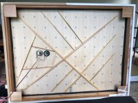
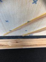
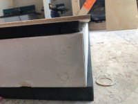
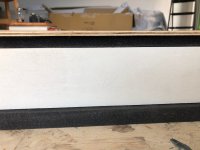
so here are some more pics.
When I said that I have a suspension but different then I wa referring to the fact that I did not suspend the edges but left them the ability to move more freely.
For now, the mounting surface is all the way around because I feared that the glue might not hold the full weight of the panel otherwise.
Also, I think if I had the luxury of a super light composite panel, then I would rather choose a irregular shape instead of a rectangle for the frame, to avoid too few resonances.
This is the purple curve speaker.
Sebastian
Attachments
I forgot something here. Similarly to such cross bar (sticks), is something that i also have on my list for for testing, once I have the new exciters and spine, is a "sound post" or "bass bar". This is known from violins and described here.Yes, it does. I assumed that this makes sense because this is where the strings are attached :-D lol.
What I have not tried yet, is to connect the big Cross brace with additional wooden "sticks" , as he mentions, to enforce the (2,1) and (3,1) modes
https://www.acs.psu.edu/drussell/Demos/rect-membrane/rect-mem.html
So much to still do, to get the lower end flatter...
Sebastian
https://acousticstoday.org/supplementary-text-violinacoustics-colin-e-gough/
I wonder if such rigid or flexible bar in the right spot from a spine to the panel, might help to enforce/ weaken particular modes.
In my case this will be affect much lower frequencies than on such small violin
Sebastian
Hello Sebastian... and all!Yes, it does. I assumed that this makes sense because this is where the strings are attached :-D lol.
What I have not tried yet, is to connect the big Cross brace with additional wooden "sticks" , as he mentions, to enforce the (2,1) and (3,1) modes
https://www.acs.psu.edu/drussell/Demos/rect-membrane/rect-mem.html
So much to still do, to get the lower end flatter...
Sebastian
You are right... so much to do and how to avoid the step too far?
Thank you for the video about guitar you posted. I watched it. In addition I like everything around wood working!
What I get out of it :
- The bridge is the input, the source of vibration. In DML the role is given to the exciter. For the guitar, the recommendation is to have it at the center for the best efficiency. Nothing says it is the same for DML where the straightness of the FR is the target. To see if an additional part is needed between the exciter and the panel.
- The balsa wood is a good candidate for soundboard but unfortunately for the guitar it doesn't have enough mechanical resistance. I read the same in a thesis about piano sound board. The requirement for DML being different, no strings, the balsa might to be considered (see after)
- The bracing is described as having two functions : creating the desired modes, increasing the mechanical resistance of the top. For DML, we search for means to spread the modes across the frequency range without increasing too much the 1st mode frequency. It would be interesting to understand what is the minimum bracing doing that. If someone has an idea.
- I saw also (and also in other video) how to hold a piece of wood in order to test its resonance (2 fingers in the 1st 1/4 1/3? of the long side).
For now, about bracing I am in the understanding it creates smaller areas having their own modes. Thanks to the asymmetry of the bracing, the areas are different so spread the mode. It might be also that the asymmetry is also good to get some efficiency of non odd, odd modes. A sort of help to the chaos! I don't know if it is right. Any opinion?
This video reinforces my idea to work with balsa. Balsa is sold in dimensions not sufficient for a panel. so we need to put different board to gather. I wonder what is the best way. I see 2 possibilities :
- Boards in parallel having the thickness of the final panel and glued by their edge as a soundboard is done for the piano or also I think for the guitar
- Plywood like assembly. So board of a lower thickness than the final, glued together. Each layer being perpendicular to the next one. It is the solution used by Veleric with if I remember a quite good result. In this technique what would be the best glue? PVA? epoxy?...
By the way, watching the video, on the other proposals from Youtube, I have seen "super glue as a wood finishing technique". Does somebody have an experience about that? The final coating of the panel is going to be a question.
Christian
Thank you Sebastian for your answer. Understood.Hello Christian,
so here are some more pics.
When I said that I have a suspension but different then I wa referring to the fact that I did not suspend the edges but left them the ability to move more freely.
For now, the mounting surface is all the way around because I feared that the glue might not hold the full weight of the panel otherwise.
Also, I think if I had the luxury of a super light composite panel, then I would rather choose a irregular shape instead of a rectangle for the frame, to avoid too few resonances.
This is the purple curve speaker.
Sebastian
I see the foam suspension is something like 15mm from the edge. On my plywood panel it is just at the edge.
I see also the grain of the external layer of the plywood is in the direction of the short side. This goes in the way to increase the difference of the 2 directions. The long side got the lowest bending stiffness, the short one the highest; I don't know if it makes a difference from other designs... To be kept in mind.
About irregular shapes, nothing clear for now for me... My only experience is that an oval shape (fully symetric) seems to concentrate modes, a rectangular shape (also axially symetric) with the short sides cut in a concave shape (the dimension at the central line is shorter than the edges) seems be more even in FR. Just some quick tests with pieces of XPS done...
Christian
PS : putting together this discussion about irregular shapes and the video you posted showing the violin mode :
- As mentioned above, a concave shape on the short side of a rectangular shape seems flatter in FR than a full rectangular
- Not mentioned above but I have somewhere a test showing the benefit on the FR straightness of rounded corners
- And putting all of that together, might we see in the guitar or the violin shape some asymmetric rectangle with rounded corner and concave long side?
Last edited:
Besides balsa, there is another species called 'Paulownia' or Chinese Empress Tree. It was the subject of some investment schemes in Australia, as a fast-growing plantation timber that captures carbon. Most went bust I believe but there are a couple of places selling the timber for eg surfboards. A little denser than balsa but a higher strength-to-weight. Looks like you can buy in widths up to 300 mm. Also, cheaper than balsa I think.Hello Sebastian... and all!
You are right... so much to do and how to avoid the step too far?
Thank you for the video about guitar you posted. I watched it. In addition I like everything around wood working!
What I get out of it :
- The bridge is the input, the source of vibration. In DML the role is given to the exciter. For the guitar, the recommendation is to have it at the center for the best efficiency. Nothing says it is the same for DML where the straightness of the FR is the target. To see if an additional part is needed between the exciter and the panel.
- The balsa wood is a good candidate for soundboard but unfortunately for the guitar it doesn't have enough mechanical resistance. I read the same in a thesis about piano sound board. The requirement for DML being different, no strings, the balsa might to be considered (see after)
- The bracing is described as having two functions : creating the desired modes, increasing the mechanical resistance of the top. For DML, we search for means to spread the modes across the frequency range without increasing too much the 1st mode frequency. It would be interesting to understand what is the minimum bracing doing that. If someone has an idea.
- I saw also (and also in other video) how to hold a piece of wood in order to test its resonance (2 fingers in the 1st 1/4 1/3? of the long side).
For now, about bracing I am in the understanding it creates smaller areas having their own modes. Thanks to the asymmetry of the bracing, the areas are different so spread the mode. It might be also that the asymmetry is also good to get some efficiency of non odd, odd modes. A sort of help to the chaos! I don't know if it is right. Any opinion?
This video reinforces my idea to work with balsa. Balsa is sold in dimensions not sufficient for a panel. so we need to put different board to gather. I wonder what is the best way. I see 2 possibilities :
- Boards in parallel having the thickness of the final panel and glued by their edge as a soundboard is done for the piano or also I think for the guitar
- Plywood like assembly. So board of a lower thickness than the final, glued together. Each layer being perpendicular to the next one. It is the solution used by Veleric with if I remember a quite good result. In this technique what would be the best glue? PVA? epoxy?...
By the way, watching the video, on the other proposals from Youtube, I have seen "super glue as a wood finishing technique". Does somebody have an experience about that? The final coating of the panel is going to be a question.
Christian
https://bywaterdesign.com.au/paulownia-sales
https://barenakedboards.com.au/paulownia-timber-sales
As a soundboard:
http://www.anzlf.com/viewtopic.php?t=6762
I imagine the bracing would break up the waves with partial transmission and partial reflection, randomising and reducing opportunities for strong resonance. Similar goals as I'm trying for with more complex shapes.
When I first saw the bracing it reminded me of a fractal pattern, or dendritic growth in crystals. Not sure I would hide it, but rather put it on the front side as a feature 🙂
It would also be interesting to check whether the sound from the back has a similar spectrum and level. May be higher SPL from the back.
Last edited:
Hi Lebo,
Since you can 3D print panels you should try incorporating magnetic suspension at each corner and if you do a large panel on the half way point along the long edge of the panel. This gives quite a remarkable damping response without contacting the panel. It also give a very nice aesthetic appeal having a panel suspended in the frame. I am currently working on a servo feedback current amplifier to drive the exciter to give a real linear response of the panel .
Cheers,
Steve
Hello Christian,Thank you Sebastian for your answer. Understood.
I see the foam suspension is something like 15mm from the edge. On my plywood panel it is just at the edge.
I see also the grain of the external layer of the plywood is in the direction of the short side. This goes in the way to increase the difference of the 2 directions. The long side got the lowest bending stiffness, the short one the highest; I don't know if it makes a difference from other designs... To be kept in mind.
About irregular shapes, nothing clear for now for me... My only experience is that an oval shape (fully symetric) seems to concentrate modes, a rectangular shape (also axially symetric) with the short sides cut in a concave shape (the dimension at the central line is shorter than the edges) seems be more even in FR. Just some quick tests with pieces of XPS done...
Christian
PS : putting together this discussion about irregular shapes and the video you posted showing the violin mode :
- As mentioned above, a concave shape on the short side of a rectangular shape seems flatter in FR than a full rectangular
- Not mentioned above but I have somewhere a test showing the benefit on the FR straightness of rounded corners
- And putting all of that together, might we see in the guitar or the violin shape some asymmetric rectangle with rounded corner and concave long side?
I have just little today.
Just to avoid misinterpretations on your end.
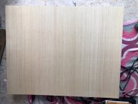
The "grain" direction you assume to see on my panels is just a thinner than paper veneer. I have no idea how they manage to get this so evenly and without impurities onto the plywood sheets.
It does not take much to damage that delicate layer.
I still have some cut offs laying around here.I can try to peel/sand them off to show you the true grain direction of the outer layers of the sheet, if you like?
Sebastian
Hello TagisHi Lebo,
Since you can 3D print panels you should try incorporating magnetic suspension at each corner and if you do a large panel on the half way point along the long edge of the panel. This gives quite a remarkable damping response without contacting the panel. It also give a very nice aesthetic appeal having a panel suspended in the frame. I am currently working on a servo feedback current amplifier to drive the exciter to give a real linear response of the panel .
Cheers,
Steve
a current feedback is my list of possible improvement too. Might be a good topic for a new thread.
What about the stability?
Christian
Nice idea. Have given up on the printed plates since I could not get good sensitivity. It was on better than the 4mm plywood, but after trying EPS the printed plates seemed pointless, even if you probably could tweak them to get a quite good FR and sound.Hi Lebo,
Since you can 3D print panels you should try incorporating magnetic suspension at each corner and if you do a large panel on the half way point along the long edge of the panel. This gives quite a remarkable damping response without contacting the panel. It also give a very nice aesthetic appeal having a panel suspended in the frame. I am currently working on a servo feedback current amplifier to drive the exciter to give a real linear response of the panel .
Cheers,
Steve
Thank you for the precision Sebastian.Hello Christian,
I have just little today.
Just to avoid misinterpretations on your end.
The "grain" direction you assume to see on my panels is just a thinner than paper veneer. I have no idea how they manage to get this so evenly and without impurities onto the plywood sheets.
It does not take much to damage that delicate layer.
I still have some cut offs laying around here.I can try to peel/sand them off to show you the true grain direction of the outer layers of the sheet, if you like?
Sebastian
Going back in the post, there is this Veleric post #3181 showing revply also. I can't find by now the link to this material
Christian
About HF
Just to add an element to the "high frequency" topic. Today, I made a new FR of my canvas panel (see below). The HF above 10k is higher than what I get with other panels. Here, there are 2 layers of 1mm balsa (the pad of this canvas panel) behind the canvas itself. It is the same exciter I use on the plywood panel (DAEX25FSHE-4). One difference here, it is epoxy glue.

Just to add an element to the "high frequency" topic. Today, I made a new FR of my canvas panel (see below). The HF above 10k is higher than what I get with other panels. Here, there are 2 layers of 1mm balsa (the pad of this canvas panel) behind the canvas itself. It is the same exciter I use on the plywood panel (DAEX25FSHE-4). One difference here, it is epoxy glue.
That is cool! I don't think I saw Valeric's panels before. It looks like he did merely the same thing, but kept the corners unsuspended.Thank you for the precision Sebastian.
Going back in the post, there is this Veleric post #3181 showing revply also. I can't find by now the link to this material
Christian
The sheets i bought are here:
https://www.lowes.com/pd/SurePly-1-4-in-Whitewood-Plywood-Application-as-4-x-8/50124674
They are also available in 8fx4ft and unfortunately, if i would have know that this all works out so great, I might have gone with the bigger version. My sloped ceiling has enough space. But I also need some space for sound treatment....
May be for the house walls towards the backyard :-D
Sebastian
Last edited:
- Home
- Loudspeakers
- Full Range
- A Study of DMLs as a Full Range Speaker