Leob.
use headphones when listening to the recordings , very important !
the microphone was at 1m and I was at 3m , almost at the point of putting my fingers in my ears 😁😁
Steve.
use headphones when listening to the recordings , very important !
the microphone was at 1m and I was at 3m , almost at the point of putting my fingers in my ears 😁😁
Steve.
Leob.
actually over on page 117 there are recordings of drums and trumpets and Dr main granche( one for Christian) all at extreme volume levels.
the French female vocals I use as a torcher track(not because she is French 😁) because she really belts it out ,no restraint !!
you can listen to this as loud as you like , it just sounds better.
Steve.
Hi Folks,
I’ve had a skim through this thread and have convinced myself I want to give these DML’s a go. Beyond that I have very little knowledge 😂😅.
But in the true spirit of just give it a go, what exciters and first go panels would you folk suggest? I’m very much a hands on, make it first, then learn about it kind of guy. Then the next build just gets better.
Also I love the look of the Tall Blondes, did that design ever get fine tuned at all?
Cheers!
Was a bit discouraged with the printed panels yesterday and the apparent dullness compared to the PC panel or my regular speakers.
Now I think you might been right all along Steve, and the PC is really harsh sounding, but the response of the 50mm exciter is tilted towards the low end, making them somewhat balanced.
With some EQ, the printed panel sounds better than the PC panel for sure, and is much louder.
Now I think you might been right all along Steve, and the PC is really harsh sounding, but the response of the 50mm exciter is tilted towards the low end, making them somewhat balanced.
With some EQ, the printed panel sounds better than the PC panel for sure, and is much louder.
Leob.1/2 mil card
I fairly quickly put together two similar card panels .
one is a single card ,about half a mil thick with a layer of toilet paper soaked in pva (half a ply per side )on each side.
the other panel is two ply 1 mil card glued together with pva and coated with toilet paper and pva (the very cheep thin stuff ,not your expensive soft thick fluffy paper,Im not made of money!).
they are both around 10 1/2 inches in size(i do have smaller panels with similar performances ).
also i have slightly altered the exciter so that it now has a 2cm hard dome in the middle of the coil area,i have been testing this out on different types of panel for some years now,it is much easier on the thinner materials.
I chose this track from another USHER sample cd which they used to hand out at the audio shows ,she really belts out the vocals in places ,as usual i played this fairly loud and as usual a little too close to the LF speakers although they XO at 250hz ,
the panels were run full range but the response was well down below 250hz but still a useful output.
I have not finished putting these together yet,so they are still an ongoing project ,but thought i would show how just a little quick effort can produce worthwhile results.
hope you all find it interesting .
steve
This as it states is 1mm card ply.
the ones before were test eps panel.
on post 2338 there are picture of the card panels.
Steve.
Hello Mitch311Hi Folks,
I’ve had a skim through this thread and have convinced myself I want to give these DML’s a go. Beyond that I have very little knowledge 😂😅.
But in the true spirit of just give it a go, what exciters and first go panels would you folk suggest? I’m very much a hands on, make it first, then learn about it kind of guy. Then the next build just gets better.
Also I love the look of the Tall Blondes, did that design ever get fine tuned at all?
Cheers!
I take the opportunity of your post to up date the "history file" I try to keep.
You may find information to help you do your shopping... It is for sure not exhaustive and it is colored by what I have in mind. Hopefully better than nothing.
I saw some days ago a document posted describing the Tall Blonde but I didn't note the link... so if somebody can tell me where iti is...
From my short experience and if in addition you love the Tall Blode styling, plywood might be a good starting point. It doesn't have the efficiency we are dreaming but it might be a good starting point. If you want a clean, nice panel for your living room, you'll neeed some frame against warping if you adopt low thickness like 3mm. Easy to build but off the main track is the canvas panel with the advantage of its low surface.
About the exciter, I have nothing to say against the Dayton Audio DAEX25FHE-4 I use... neither to say it is the one to use! My choice was a not too big coil diameter to be able to reach the high frequencies. This one can do it, other also (see in posts somewhere before the comparison with the Tectonic Spedge uses. At the end it will be perhaps your retailer list and the availability that will make the choice.
Christian
Attachments
Leob
there are recordings using canvas panels and other types.
If you can find them.
it's not the easiest site to search, even for me !
Steve.
there are recordings using canvas panels and other types.
If you can find them.
it's not the easiest site to search, even for me !
Steve.
Leob,After testing the printed panel a bit more carefully, it is pretty dead above 3-4k.
I was mostly worried about the bass due to the small size, but I guess the material just has the wrong properties. It is of course nowhere near as stiff as plywood or PC/Acrylic, which I guess is the problem. I'm trying to print a plate with thinner surface and using PETG instead of PLA+, but expecting it to be quite similar. Stiffness will not be very different, and I'm guessing modifying thickness or density will not really help much either.
While most thermoplastics used in 3d printing is in the same ballpark when it comes to material specs, there are some specialized materials that claim to improve for example stiffness. The cheap PLA+ I'm using doesn't have specs, but I have PETG and BioFusion from extrudr, and they have specs on their website.
Looking at the specs for BioFusion its tensile modulus is 3200 MPa and their PETG is 3100 MPa. The stiffest I found with reasonable price and that is easily printable is nanodiamond filament which claims 6800 MPa: https://carbodeon.com/product/udiamond/
A bit trickier to print perhaps, but CA-PAHP claims 25GPa: https://treedfilaments.com/3d-printing-filaments/pahp-carbon-3d-printing-filament/
Thinking if I will give the latter a go, it seems to have quite radically different properties than your typical filament at least. And with my level of understanding in material science, shooting blindly in different directions and see what sticks seems like a good strategy 🙂
3D printing is far from what I know. Could you post some CAD views, pictures of your panels? Some frequency response would also help?
About the material choice, I am pretty sure we haven't listed all. Stiffness through the tensile modulus and the geometry is one, then is the aerial density from the density and the geometry again. Somewhere in the shadow we should find the damping or absorption.
Christian
Here is the patent info on the ear shape panel J. Bertagni, “Flat Diaphragm for Sound Transducers,” US Patent 3,722,617 (1973 Mar.).
Here is the patent US20030081799A1which has several interesting points :
If a panel has an audible self-noise, something should be visible with this kind of test.
The frequency response shown is said of good performance... it is really similar to what we get from different panels in this thread

Christian
- A general discussion about DML, their qualities
- The description of a sandwich membrane made of a kraft honeycomb core with high tensile strength skins and special attention to the adhesive with high efficiency, high power capability, low self noise, low end.
- an evaluation of the self noise performance of a panel.
If a panel has an audible self-noise, something should be visible with this kind of test.
The frequency response shown is said of good performance... it is really similar to what we get from different panels in this thread
Christian
Very busy last few days preparing for a gig this weekend, so didn't get around to taking pictures yet, but will do.Leob,
3D printing is far from what I know. Could you post some CAD views, pictures of your panels? Some frequency response would also help?
About the material choice, I am pretty sure we haven't listed all. Stiffness through the tensile modulus and the geometry is one, then is the aerial density from the density and the geometry again. Somewhere in the shadow we should find the damping or absorption.
Christian
And have no measuring mic yet, so just going by my ears and doing some EQ sweeps it does seem very lacking above 3-4k as well as below 400hz. I confused myself when comparing to the PC panels, because they seem complement each other in their deficiencies. Obviously they are both sub-optimal materials though.
Trying to figure out the optimal material through specs seems very hard, but I have the feeling that thermoplastics in general doesn't have the right characteristics. Maybe gonna try this as a last attempt since it seems easy to print and I will have use for it anyway: https://www.extrudr.com/en/products/catalogue/greentec-pro-carbon_2410/
But really seems like I should focus on composites or foams like XPS.
Christian.
yes that frequency plot is very familiar with certain types of panel.
it was nice to read a patent that I could understand, more modern patents seem to want to confuse and hide and be vague about what they are saying ?
Bury the meaning in words !
So what is he really doing.
In the past I have used damping in the form of vinyl silk ,silicon, neat pva, and more.
But this is all added weight, in this patent he is replacing the hard glue with a softer more rubbery glue, so now you have the damping without the extra weight.
This is a great idea, but it is still damping.
I suspect this will have an adverse effect on the sound, for me anyway ?
One thing I would be suspicious of ,would be the extra bounce it would cause in the panel itself.
I have found this problem when using silicone as a coating ,would it have the same effect internally?
so something maybe that would add damping ,but not bounce to the panel ?
there is a lot of generalizing in this patent,which I would take with a pinch of salt.
Steve.
Leob.
how thin can one of those printers make the honey comb skin and surface skins ?
it would be very interesting to know how a carbon printed panel would sound and perform ?
Steve.
how thin can one of those printers make the honey comb skin and surface skins ?
it would be very interesting to know how a carbon printed panel would sound and perform ?
Steve.
Minimum layer height is usually considered around 0.1 mm. With the right printer and nozzle you can get less, but that carbon filament specifies it needs at least 0.5mm nozzle, so I think it might even need a bit higher.Leob.
how thin can one of those printers make the honey comb skin and surface skins ?
it would be very interesting to know how a carbon printed panel would sound and perform ?
Steve.
To get a uniform surface you probably want at least 2 layers though, one with the lines printed in each direction, so 0.2 mm per surface.
If I just make a rectangle (or whatever shape) and then import it to the slicing software used to prepare the 3d object for the printer, I can select different infills and set their density there. So for example 20% honeycomb. It will then fill everything between the solid fills with infill, so if each surface is 0.2 mm I get 0.6 mm infill if my model was 1 mm.
Typically carbon filaments are basically 10-20 carbon dust with plastic. So material properties will be quite far off from an actual carbon sheet. There are some expensive industrial printers that have one extruder for plastic and one for actual long carbon fibers, and they can be used to make actual proper carbon sheets, but when mixed in already with the plastic, fibers have to be very short.
The one I linked to seems to have relatively long fibers though and more than double the stiffness compared to typical thermoplastics.
Steve,Christian.
yes that frequency plot is very familiar with certain types of panel.
it was nice to read a patent that I could understand, more modern patents seem to want to confuse and hide and be vague about what they are saying ?
Bury the meaning in words !
So what is he really doing.
In the past I have used damping in the form of vinyl silk ,silicon, neat pva, and more.
But this is all added weight, in this patent he is replacing the hard glue with a softer more rubbery glue, so now you have the damping without the extra weight.
This is a great idea, but it is still damping.
I suspect this will have an adverse effect on the sound, for me anyway ?
One thing I would be suspicious of ,would be the extra bounce it would cause in the panel itself.
I have found this problem when using silicone as a coating ,would it have the same effect internally?
so something maybe that would add damping ,but not bounce to the panel ?
there is a lot of generalizing in this patent,which I would take with a pinch of salt.
Steve.
Sorry, my understanding of English let me unsure of what you mean : "with a pinch of salt" = to take cautiously? I understand we have the same feeling. My knowledge about composite membrane is to low to have an opinion about it but i found the spectral contamination test interesting. Here are some results with the material I have at home.
I played the 30 frequency signal from Linear Audio (see 4651) and displayed the spectrum thanks to REW with the mic at about 2m.
All the peaks between 2 frequencies of the signal mean non linearity or self noise.
First the noise floor (no speaker playing). Not really good but no time to search for improvement. The peaks may come from the switching supply of my laptop and also from its fan (not far enough from the mic):
As a reference a cone full range : a FRS8 Visaton
My plywood panel:
My canvas panel :
A cardboard
An XPS 9mm sheet not sanded nor coated:
An EPS 20mm sanded and coated:
The "glass" in front of an IKEA frame (acrylic?)
Some post treatment might help, we could also think to a metric but in the first reading, we could see a correlation with the opinion about the different materials...
Christian

About the SPL at 2m for different materials
Other today test : about "efficiency". Or in other words trying to understand which characteristics of a panel make the SPL.
For that, I played a 200Hz to 5kHz pink noise and measure the SPL at 2m in dBA, all of that with REW.
As a reference, I use a FRS8 Visaton. All the settings were kept the same during the test; Only the material was changed.
The main results :
I tried to see a logic in that with the density and the Young modulus to have characteristics not linked to the geometry. This allows to sort the material in almost the order coming from the test but it doesn't completely fits as figure.
All of that is perhaps already known... it was not my case...
So if somebody as the knowledge or even an idea to link that to some physics, I'll appreciate.
Christian
Other today test : about "efficiency". Or in other words trying to understand which characteristics of a panel make the SPL.
For that, I played a 200Hz to 5kHz pink noise and measure the SPL at 2m in dBA, all of that with REW.
As a reference, I use a FRS8 Visaton. All the settings were kept the same during the test; Only the material was changed.
The main results :
- I started with a 60x80cm sheet of 9mm XPS (the one in the posts before that doesn't work...) and then tested the half, and he half... five tests to finish with a 15x10cm. The result is that the bandwith is reduced each time the surface is divided but the level in the bandwith doesn't change really (+/-1dB). So from this test, the SPL is not strongly dependent of the area.
- Second observation : I have a group of PS sheets (EPS 20mm, XPS 20mm, XPS 9mm, XPS 5mm) and a group of plywood sheets (3mm, 4mm, 10mm). In each group, the SPL are close. So low dependency to the thickness. The efficiency of the plywood is similar to the FRS8 (which is a low efficiency loudspeaker), the PS group is about 8dB above.
- Third observation : the 1mm "glass" (acrylic?) from an IKEA frame which has the highest density among what I tested and which is also not stiff has the lowest efficiency. Its efficiency is 5dB below the plywood! The plywood which in its 10mm is an heavy sheet but also stiff seems to keep the efficiency of the 3mm.
I tried to see a logic in that with the density and the Young modulus to have characteristics not linked to the geometry. This allows to sort the material in almost the order coming from the test but it doesn't completely fits as figure.
All of that is perhaps already known... it was not my case...
So if somebody as the knowledge or even an idea to link that to some physics, I'll appreciate.
Christian
Quick question here... I am about to finally try testing some panels of different materials. I have settled on 50x30 cm panel size due to some sheets I already have. The frame will be the same for each using foam on edges for support and the different materials will be swapped out using the same exciter.
The question is how do people mount the exciters so panels can be swapped? I am a bit loathe to use the supplied double sided tape as I dont think it is intended to be removed and reapplied. I will have some sort of wood mounting structure to support the exciter (to be determined) but wondering how to couple the exciter to the panel. I have an assortment of Dayton exciters to try out and have just ordered some of the Aiyamas from Aliexpress as well.
Panels will be
I am thinking some sort of silicone or polyurethane sealer which has low strength. Of course once I decide on the best material I will use something stronger.
The question is how do people mount the exciters so panels can be swapped? I am a bit loathe to use the supplied double sided tape as I dont think it is intended to be removed and reapplied. I will have some sort of wood mounting structure to support the exciter (to be determined) but wondering how to couple the exciter to the panel. I have an assortment of Dayton exciters to try out and have just ordered some of the Aiyamas from Aliexpress as well.
Panels will be
- 2mm Nomex honeycomb with wood veneer on each side
- 5mm end grain balsa
- 3mm bass wood plywood
I am thinking some sort of silicone or polyurethane sealer which has low strength. Of course once I decide on the best material I will use something stronger.
Tsardoz.
For testing panels no framework is needed.
I use the methods in the photos when testing exciters and panels using ordinary double sided tape .
they could last hours or days.
for permanent fixing I use pva .
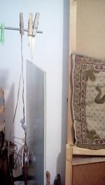
The first three photos are of my 5mm epoxy coated xps using masking tape to support the panel and pegs to hold the tape and lead out wires
I've twisted them around so you can see.
This is the usual place where I mount my panels.
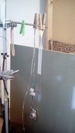
You could also use the masking tape stuck to the back of the exciter to the mounting at the top for added safety.
You can adjust the tension ,how much weight is supported by using the pegs.
The fourth picture is of a polystyrene panel with a permanent sponge attached to the panel.
I just use a peg to attach this to whatever I want, this is my preferred panel mounting as it stops the panel swinging around every time I walk by it.
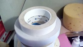
The fifth photo is of a couple of tapes I have use ,one unbranded.
Not all double sided tapes are the same ,some are better than others, but all should last for enough time for testing.
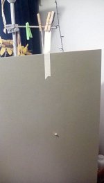
The sixth photo is an old panel I found with the tape still on it, I have to use two pieces of tape as the tape is not wide enough.
It is always a good idea to have the exciter wires firmly secured at the top in case the exciter does fall off and crashes to the floor !!
If measuring ,I would mount the panel in the best sounding place in the room, hopefully this is where you will permanently mount them ?
Measuring them in a place where they sound bad is not a good idea !
Steve.
For testing panels no framework is needed.
I use the methods in the photos when testing exciters and panels using ordinary double sided tape .
they could last hours or days.
for permanent fixing I use pva .
The first three photos are of my 5mm epoxy coated xps using masking tape to support the panel and pegs to hold the tape and lead out wires
I've twisted them around so you can see.
This is the usual place where I mount my panels.
You could also use the masking tape stuck to the back of the exciter to the mounting at the top for added safety.
You can adjust the tension ,how much weight is supported by using the pegs.
The fourth picture is of a polystyrene panel with a permanent sponge attached to the panel.
I just use a peg to attach this to whatever I want, this is my preferred panel mounting as it stops the panel swinging around every time I walk by it.
The fifth photo is of a couple of tapes I have use ,one unbranded.
Not all double sided tapes are the same ,some are better than others, but all should last for enough time for testing.
The sixth photo is an old panel I found with the tape still on it, I have to use two pieces of tape as the tape is not wide enough.
It is always a good idea to have the exciter wires firmly secured at the top in case the exciter does fall off and crashes to the floor !!
If measuring ,I would mount the panel in the best sounding place in the room, hopefully this is where you will permanently mount them ?
Measuring them in a place where they sound bad is not a good idea !
Steve.
Attachments


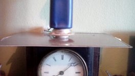
I have just glued my exciter to my small corrugated cardboard and epoxy panel,using pva.
I have placed a small amount of weight on the exciter to make sure of a good contact between the exciter and panel surface.
I have placed it over the fireplace so it should cure quicker and also I gave it a quick blast with the hair dryer.
hopefully it will be alright for a test tomorrow, but it will be a good few days before it is fully dry.
Steve.
Attachments
- Home
- Loudspeakers
- Full Range
- A Study of DMLs as a Full Range Speaker