Christian.
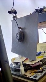
These are some photos of the 1mm corrugated panel ,I have coated the exciter side with a little neat pva and used that to glue the exciter in place.
I used a hair dryer to dry the pva quickly and then paced weights to flatten the panel and stop it bowing, when I do the other side it will try to bow it the other way.
I did intend to listen to the naked panel without the pva , but I could not wait !
There is a little exciter noise at about 1.6k , which I think is the spider ? This panel might be sensitive to this ?
But I will deal with that later.
I had to turn the volume down 3db to match the output of my 85cm x 60cm 5mm xps and epoxy panel.
So the card is more efficient and also sounds more alive , I think ?
It's early days ,and there is a lot more I can do to improve things, next I will pva the front side and see if this improves things or not ?
I will round the corners ,mainly because I think it looks prettier and may prevent wobbling in the corners a little ?
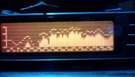
Anyway, my first impressions are very good, it covers the frequencies from 160hz to 20k , and actually plays down to 50hz on real music,
I can't hear any nasty sounds yet ,but I have only had a quick listen.
The microphone was at 1m and I left on the peak hold using pink noise.
Steve.
These are some photos of the 1mm corrugated panel ,I have coated the exciter side with a little neat pva and used that to glue the exciter in place.
I used a hair dryer to dry the pva quickly and then paced weights to flatten the panel and stop it bowing, when I do the other side it will try to bow it the other way.
I did intend to listen to the naked panel without the pva , but I could not wait !
There is a little exciter noise at about 1.6k , which I think is the spider ? This panel might be sensitive to this ?
But I will deal with that later.
I had to turn the volume down 3db to match the output of my 85cm x 60cm 5mm xps and epoxy panel.
So the card is more efficient and also sounds more alive , I think ?
It's early days ,and there is a lot more I can do to improve things, next I will pva the front side and see if this improves things or not ?
I will round the corners ,mainly because I think it looks prettier and may prevent wobbling in the corners a little ?
Anyway, my first impressions are very good, it covers the frequencies from 160hz to 20k , and actually plays down to 50hz on real music,
I can't hear any nasty sounds yet ,but I have only had a quick listen.
The microphone was at 1m and I left on the peak hold using pink noise.
Steve.
Attachments

Thank you for this feedback Steve.Christian.
These are some photos of the 1mm corrugated panel ,I have coated the exciter side with a little neat pva and used that to glue the exciter in place.
I used a hair dryer to dry the pva quickly and then paced weights to flatten the panel and stop it bowing, when I do the other side it will try to bow it the other way.
I did intend to listen to the naked panel without the pva , but I could not wait !
There is a little exciter noise at about 1.6k , which I think is the spider ? This panel might be sensitive to this ?
But I will deal with that later.
I had to turn the volume down 3db to match the output of my 85cm x 60cm 5mm xps and epoxy panel.
So the card is more efficient and also sounds more alive , I think ?
It's early days ,and there is a lot more I can do to improve things, next I will pva the front side and see if this improves things or not ?
I will round the corners ,mainly because I think it looks prettier and may prevent wobbling in the corners a little ?
Anyway, my first impressions are very good, it covers the frequencies from 160hz to 20k , and actually plays down to 50hz on real music,
I can't hear any nasty sounds yet ,but I have only had a quick listen.
The microphone was at 1m and I left on the peak hold using pink noise.
Steve.
2 questions (quickly... I have to go back to other activities!)
- which exciter position did you choose?
- I understand you glue the exciter (and many other things!) with PVA on the membrane. Right? Is it an alternative for you to the double side tape without coming to epoxy (like I did for my canvas and being afraid if I could remove the exciter...)?
Christian.
I just glued the exciter in the centre of the panel, the beauty of card panels is that you can cut the shape and size to whatever you like and when you like.
I even recorded my small heart shaped panel .
this panel seems to cope well with the exciter in the centre, I did make a video recording of the panel vibrating while playing a 50hz bass guitar, but I don't have time to figure out how to get it shown !
I have only use pva to glue my exciters onto my panels, and some have been on my panels for over 10years.
I would not use the sticky tape supplied with the exciter , I prefer a solid mounting.
I only use double sided tape for quick testing.
With card you don't have to worry about damaging the card, just throw it from and start again.
A Stanley knife usually helps peel off the exciter.
Pva is never quite rigid like superglue but it works very well , and it is being glued on to a pva coated panel anyway .
Steve.
SteveChristian.
I just glued the exciter in the centre of the panel, the beauty of card panels is that you can cut the shape and size to whatever you like and when you like.
I even recorded my small heart shaped panel .
this panel seems to cope well with the exciter in the centre, I did make a video recording of the panel vibrating while playing a 50hz bass guitar, but I don't have time to figure out how to get it shown !
I have only use pva to glue my exciters onto my panels, and some have been on my panels for over 10years.
I would not use the sticky tape supplied with the exciter , I prefer a solid mounting.
I only use double sided tape for quick testing.
With card you don't have to worry about damaging the card, just throw it from and start again.
A Stanley knife usually helps peel off the exciter.
Pva is never quite rigid like superglue but it works very well , and it is being glued on to a pva coated panel anyway .
Steve.
I didn't think PVA would glue to the coil. Nice to know.
About the first frequency response... not a bit "unstable"?
Christian
Christian.
don't panic !
these were just quick measurements in a very crowded room.
I was more interested in how much of the frequency range was being covered.
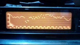
I struggled to get this measurement,climbing over a lot of junk in my room ,so ignore everything below 100hz.
If you disregard the hump in about the 2k area which I believe is exciter noise and I do include the spider noise that you were having.
I know this because I was trying to move the panel left and right to see how the response changed, but as soon as I placed my hand anywhere near the back of the exciter the hump increased in size.
The sound is coming through the panel and off the back wall, although I have not heard any nasty sounds when playing music.
If you look at the plot ,you will see that mainly the response stays within the 5db lines from at least 200hz to 10k that is if this hump is removed ?
This measurement was at 3m into the room moving the microphone to the left and right which fills in the response down to below 200hz.
The hf rolls off a little above 10k but then comes back up to 20k.
I have seen this problem before and I think I can improve on this ,with a little fiddling around ?
I have had a chance to listen to this panel today and so far I have not heard any nasty sounds.
Bells and cymbals ,voice ,saxophone, they all sound very natural ,which is the main objective as far as I am concerned, but it would be nice to flatten out that response, for peace of mind.
Steve.
don't panic !
these were just quick measurements in a very crowded room.
I was more interested in how much of the frequency range was being covered.
I struggled to get this measurement,climbing over a lot of junk in my room ,so ignore everything below 100hz.
If you disregard the hump in about the 2k area which I believe is exciter noise and I do include the spider noise that you were having.
I know this because I was trying to move the panel left and right to see how the response changed, but as soon as I placed my hand anywhere near the back of the exciter the hump increased in size.
The sound is coming through the panel and off the back wall, although I have not heard any nasty sounds when playing music.
If you look at the plot ,you will see that mainly the response stays within the 5db lines from at least 200hz to 10k that is if this hump is removed ?
This measurement was at 3m into the room moving the microphone to the left and right which fills in the response down to below 200hz.
The hf rolls off a little above 10k but then comes back up to 20k.
I have seen this problem before and I think I can improve on this ,with a little fiddling around ?
I have had a chance to listen to this panel today and so far I have not heard any nasty sounds.
Bells and cymbals ,voice ,saxophone, they all sound very natural ,which is the main objective as far as I am concerned, but it would be nice to flatten out that response, for peace of mind.
Steve.
Attachments
Good SteveChristian.
don't panic !
these were just quick measurements in a very crowded room.
I was more interested in how much of the frequency range was being covered.
I struggled to get this measurement,climbing over a lot of junk in my room ,so ignore everything below 100hz.
If you disregard the hump in about the 2k area which I believe is exciter noise and I do include the spider noise that you were having.
I know this because I was trying to move the panel left and right to see how the response changed, but as soon as I placed my hand anywhere near the back of the exciter the hump increased in size.
The sound is coming through the panel and off the back wall, although I have not heard any nasty sounds when playing music.
If you look at the plot ,you will see that mainly the response stays within the 5db lines from at least 200hz to 10k that is if this hump is removed ?
This measurement was at 3m into the room moving the microphone to the left and right which fills in the response down to below 200hz.
The hf rolls off a little above 10k but then comes back up to 20k.
I have seen this problem before and I think I can improve on this ,with a little fiddling around ?
I have had a chance to listen to this panel today and so far I have not heard any nasty sounds.
Bells and cymbals ,voice ,saxophone, they all sound very natural ,which is the main objective as far as I am concerned, but it would be nice to flatten out that response, for peace of mind.
Steve.
Which is also very interesting is your "reading grid" of those frequency responses. You have pointed the role of the exciter with the spider at the back and the central area. There are 2 other areas in common to many FR : the hole around 150Hz (there is no big necessity to fill but it would probably better for a good filtering at 200Hz) and as you mention here the drop in HF. For the HF drop do you have an hypothesis? Might it be the area above the coincidence frequency where the panel starts beaming so the overall energy sent to the room falls?
By the way, yesterday I was on a paper about MMM (Microphone Moving Measurement) which is basically the technique you use (and I also use it with others based on logsweep). Do you have an interest for this paper here... most probably you have it already?
Christian
I resemble that remark! But now that I have found it, I've moved on to the quest for the holy grails of boundary conditions.Everyone seems to be looking for the holy grail of panel materials and spending a lot of money to try and find it.
Eric
Christian,Hello Steve,
One interesting and probably extremely intellectually challenging aspect of those loudspeakers is, beside the possibility of a very good loudspeaker, it leads us to reconsider how we understand this technical object, what we believe based on former experiences, readings and which might be in fact not true. The height of the challenge is even higher there are few parts involved and its behavior so different from other drivers.
You are right to point there is not necessary a link between the cost and the result. It is also one of our "intellectual internal filter" effect to link the result to technology and cost. Our brain is so it tries to find explanations or solutions it is at ease with.
The point is to understand, to put words on the quality if possible figures (performance, specification, characteristic) of the materials that gives satisfaction.
The difficulty is as many materials and solutions are possible, what can be reached by one DML builder risks to be difficult to share because of the origin of the material, the lack of metrics. It is much more difficult than cooking! Not mentioning some like spicy food, other not!
An other difficulty is that by the lack of strong shared basis, our activity knows "current of design" created by promising tests so it is not easy to come back to point the fork was created (ie the shellac one)
To come on a less philosophical side... when you mention your experience says "the soaked panel are too heavy" it reinforce my idea (again an intellectual model) there should be a minimal stiffness on aerial mass ratio that makes the panel working (to come on the wording of previous posts D/m or also where to put the coincidence frequency... if it exists for all materials). The other end of this ratio is given by the surface we are ready to give to the final panel.
Let us know how you appreciate those new panels.
On my side, I think to get basic figures from cardboard (stiffness, aerial mass) to bring it in the scope.
Christian
So many good points. I agree with them all, a least I think I do. Though I must admit I am not familiar with this phrase...."so it is not so easy to come back to the point the fork was created". I think I get the idea, but is it a common phrase in another language?
Eric
Christian,There are 2 other areas in common to many FR : the hole around 150Hz (there is no big necessity to fill but it would probably better for a good filtering at 200Hz) and as you mention here the drop in HF.
Regarding the common low frequency "hole": I believe the reason is often due to the low modal density of efficient modes at low frequencies. As we saw in the graphs we shared earlier, the odd, modes are the most efficient modes at low frequencies (1,1 1,3 1,5 etc). But for typical panels (with aspect ratio of 2:1 or less, say, the frequency ratio between the 1,1 and 1,3 modes is nearly 3 to 1. And the ratio between 1,3 and 1,5 modes is almost as large (about 2.5:1). So when the truly active (i.e. efficient) modes are so far apart, it's not surprising that there would be gaps in the low frequency response of most panels.
It's for this reason that lately I have been investigating panels with high aspect ratio. At an L/D of 4:1, the gaps between the lowest odd,odd modes are much, much smaller than for panels that are more square.
I think I made a related post on this topic way back when burntcoil posted his "tall blondes", so it may even be in your archive of the thread! But I'm only now getting serious about high aspect ratio panels myself.
Eric

Hello Eric. Nice to read you again. I feel like I missed something or I haven't taken notes carefully enough : would you mind to share your "holy grail" material?I resemble that remark! But now that I have found it, I've moved on to the quest for the holy grails of boundary conditions.
Eric
Christian
Eric,Christian,
So many good points. I agree with them all, a least I think I do. Though I must admit I am not familiar with this phrase...."so it is not so easy to come back to the point the fork was created". I think I get the idea, but is it a common phrase in another language?
Eric
I used the word "fork" in a meaning close it is used in software or also I think about ideas. At a time there is a main stream version or school of thought and then a variant appears creating a new stream. I call this node the fork. On this thread I am not only challenged by the panel technology but also in the use of English!
Christian
Eric,Christian,
Regarding the common low frequency "hole": I believe the reason is often due to the low modal density of efficient modes at low frequencies. As we saw in the graphs we shared earlier, the odd, modes are the most efficient modes at low frequencies (1,1 1,3 1,5 etc). But for typical panels (with aspect ratio of 2:1 or less, say, the frequency ratio between the 1,1 and 1,3 modes is nearly 3 to 1. And the ratio between 1,3 and 1,5 modes is almost as large (about 2.5:1). So when the truly active (i.e. efficient) modes are so far apart, it's not surprising that there would be gaps in the low frequency response of most panels.
It's for this reason that lately I have been investigating panels with high aspect ratio. At an L/D of 4:1, the gaps between the lowest odd,odd modes are much, much smaller than for panels that are more square.
I think I made a related post on this topic way back when burntcoil posted his "tall blondes", so it may even be in your archive of the thread! But I'm only now getting serious about high aspect ratio panels myself.
Eric
When I wrote that I thought I did to quickly... something missing was stored in my brain but not properly written. You are right, the efficiency of the modes should be somewhere behind and yes to work on proportions like the "tall blondes" might be the way. I will try to take the time to go in the past searching your post.
So we are going to have interesting root causes for the FR main peaks and holes... one is still missing for the loss of level in HF (the decreasing after generally 5k). Is as I suggested the behavior above the coincidence frequency a good candidate ?
Christian
Christian,would you mind to share your "holy grail" material?
You took the bait, as I hoped you would! Of course I will be happy to share details about my holy grail. I have mentioned it before, I suspect, but perhaps not described it in much detail.
It is a carbon fiber skinned, basla core sandwich composite. The top and bottom cf skins are 190 g/m2 carbon fiber fabric with epoxy resin matrix. These densify to about 0.23 mm each. The core is 1.6 mm thick balsa, with a density of about 160 g/cm^3.
I make these panels myself in my workshop. I will share more details of the process if anyone truly would like to try it themselves. But the basic process goes like this:
1. Lay the first layer of cf fabric on a glass plate, saturate it with epoxy, and apply the balsa on top.
2. Apply "peel ply" and absorbant batting layers, then put it all in a vacuum bag.
3. Apply vacuum, then let the epoxy cure overnight.
4. Remove everything from the vacuum bag, remove the peel ply and batting.
5. Apply the second layer of cf fabric on top of the balsa face, and saturate it with epoxy.
6. Repeat steps 2-4.
7. Carefully peel the composite sandwich from the glass.
With this process I end up with one glossy side (the first cf layer that was directly against the glass, while the other side is matte and has the texture of the peel ply fabric impressed into it.
Some pics of the process are attached, more info to follow.


Some more details on my cf skinned balsa core panels.would you mind to share your "holy grail" material?
Thickness: 2.1 mm
Elastic Modulus: 27 GPa
Density: 450 kg/m^3
Stiffness (D): 20 Nm
Areal Density (mu): 0.95 kg/m^2
D/mu^3: 23
Fc: 4100 Hz
Size: 584 mm x 406 mm
Of course, to call these panels the holy grail is a huge overstatement. However, they do meet my goal, which was to have a panel with a sound as good and clear as wood but with much higher efficiency. I find they do indeed sound as good as wood, and put out about 6 dB more (if I recall correctly) than plywood at the same volume setting on my amp.
Already, I have an idea for an improvement. I recently learned that my cf fabric supplier has an even thinner (by half) cf fabric than I used, for a reasonable price (normally, very thin cf fabric is very expensive). Using the thinner fabric instead, with the same balsa thickness, I should be able to produce a panel that has even higher efficiency. Or, by using the thinner fabric combined with thinner balsa, I could achieve similar efficiency, but sginificantly lower stiffness, permitting similarperformance at low frequency but with a smaller panel.
Attached pic is of my prototype panel, in a test frame, when I was testing the frequency response at various distances and angles.
Eric

I used the word "fork" in a meaning close it is used in software or also I think about ideas. At a time there is a main stream version or school of thought and then a variant appears creating a new stream. I call this node the fork. On this thread I am not only challenged by the panel technology but also in the use of English!
Ahh, when there is a decision point, we say there is a "fork in the road". It's the same thing, I think. Your use of english is really quite good, I just wanted to tease you a bit..
Eric
Christian,So we are going to have interesting root causes for the FR main peaks and holes... one is still missing for the loss of level in HF (the decreasing after generally 5k). Is as I suggested the behavior above the coincidence frequency a good candidate ?
I must admit, I don't have a clear model in my mind for the loss of level in HF. I have seen it in materials with both high and low coincidence frequency (PMMA and PS foam), but perhaps there are different causes in each case. I always had a feeling that it was worse with softer materials, due the the exciter compressing the material under the coil, instead of bending the plate, but possibly there is an effect of fc as well. I'll have to look for it in the future.
Eric
Christian.
If you go back to my posts on dml open baffle for pro use you will see on my reply 51 and 52 ,the response of a 6ft hardboard panel.
51, shows the hump in response above 10k and the slow dip up to the 10k point.
52, shows the corrections that I made using simple methods ( no damping methods or mass used)
in post 54 you see my 3ft ply panel ,which has AA batteries stuck to it's front surface.
and as it states ,I used the battery masses to fill in the dips in the 100hz to 300hz region. !
Even with some of my small panels , I could extend the frequency down to 100hz without the dips, but there is always a price to pay,regarding sound quality(in my opinion) but it is a matter of taste.
We must not get confused with the room suck outs and the panel cancellations as these two problems show up in the same area,
Once again looking at this picture from my gallery in NXT RUBBISH, you can see the small dip left after using the batteries, but when moving the microphone back 3m ,the room takes its toll,
https://www.audiocircle.com/index.php?action=gallery;area=browse;image=137096
Steve
Greetings fellow DML’ers! I want to pass along something I’ve tried that seems to have some merit. It started after ordering a pair of the 3.5” 8 ohm Tectonics BMR’s. One of the first two came broken from shipping damage and so did the replacement. Since I had two unusable units, my concept was to eliminate the spider and suspension of a typical exciter and let the DML panel be the spider and suspension – to avoid wasted energy and mechanical resistance to the force of the voice coil.
I 3D printed a mount to support the driver. I put tape around the voice coil to keep it centered on the magnet while the support was glued to the panel. After that I unscrewed the mount from the glued pads, took the tape off and reassembled.
My original panels are 1” XPS with PVA coating. The attached pictures are of the experimental assembly using 1” XPS, 3/8” XPS, with and without PVA. Also a comparison of the 3/8 and 1" mounted PVA experiment and my original 1” with a Thruster with PVA.
I'd appreciate your insights, and if this has been done elsewhere, please direct me to it. Great work you have there, Veleric!
Bdjohns.
sorry to hear of all those damaged BMR units, hope you managed to get a unit in one piece ?
many years ago over on NXT RUBBISH , I did mention that it would be a good idea to get rid of the spider ,mainly because of the noise it was making.
I could have done this with my rigid ply panels, but the warping of the ply panel prevented this.
My free floating panels need a spider , maybe we need a better designed spider similar to some older designs of the past ?
How does the sound compare to a standard exciter ?
Steve.
- Home
- Loudspeakers
- Full Range
- A Study of DMLs as a Full Range Speaker