Hi there,
Very interesting project you are working with..... I need to try it. But I will make my own exciter from bottom up. I have some 140mm 3,8 kg magnet structure with copper cap in order, hope to get them late May. Also have spider and voice coils and terminal, so it is a given that I should try to make some exciters. Hopefully the ideal membrane material is fund by them, anyway I will be following this thread....
Very interesting project you are working with..... I need to try it. But I will make my own exciter from bottom up. I have some 140mm 3,8 kg magnet structure with copper cap in order, hope to get them late May. Also have spider and voice coils and terminal, so it is a given that I should try to make some exciters. Hopefully the ideal membrane material is fund by them, anyway I will be following this thread....
Attachments
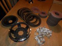
Frank40: do you fabricate the parts yourself? Judging from the magnet mass you are planning a very powerful exciter 🙂
General ideas: while DML excourages endless experimentation, I "think" that a standard model could be specified: say, a 2x2 foot panel of 3/4 XDF (brand=?) with an exciter model XXX placed at (x,y) coordinates. Suspended from two pieces of dental floss and here is the frequency sweep...
Or a simpler way to say: if anyone comes up with a configuration that makes them happy, please share in detail 🙂
Hi mexican,
Thanks for bringing up bertagni, that's very interesting.
In your drawing in post # 157, do you mean the 2 adjacent drivers are wired in opposite polarity? So they would largely cancel out the common part of the stereo signal, thus enhancing the stereo effect. Sort of ambiophonics in physical form.
I'd love to try that if time allows.
However I think of an issue (unanswered in my previous post) -- DML is pretty much bipole, which means it's the same polarity on front and rear sides. (It's so counter-intuitive but true.) So, how does the wiring polarity of the driver affect the soundwave's polarity of the panel? If the panel is bipole anyway, wiring the driver in normal or opposite way should be no difference.
I don't have proof for all that. Just thinking. What do you think?
Hi Frank40,
Your hardware looks very impressive. I'm looking forward. Please share once you have any build.
A little reminder here, although everything counts, it seems DML rely on the panel more than the driving parts. So it's advisable if you pay equal or more attention to the panel.
Hope you enjoy the journey and good luck. 🙂
I total agree.... everything count that is why I make my own driver, there is no point to have a nice driver if you do not pay attention to the membrane and suspension. The same goes for dynamic speakers.
The NTX modules that I have heard do have some lacks in my opinion, and I think it is because the lack of attention to make a rely god driver the focus has been to make them as small possible.
There is rely no difference in the energy conduction from the driver the the membrane in normal vs. NTX membranes, it is all in how the membrane load to the air.
I will post as soon as I start making driver.
Sorry Soldermizer,
I missed your question. No I do not make them my self, I order them from china and they make them after my specification.
By the way I have some sheets of Depron 100X 40 cm in thickness of 1, 2 and 3 mm have some one tried that?
I missed your question. No I do not make them my self, I order them from china and they make them after my specification.
By the way I have some sheets of Depron 100X 40 cm in thickness of 1, 2 and 3 mm have some one tried that?
Last edited:
Frank40: that is neat! Do they do it in small quantity? Please do report how your custom designs work for you.
I'm experimenting with reducing the low bass distortion on my panels. I am pretty sure it is due to the drivers currently being freely fixed (no back frame). Hanging on like lampreys to the panel 🙂 they work fine for say > 100 Hz but there is noticeable distortion < 100 Hz, and it goes away if I manually hold up the driver. So some type of a frame is needed to (I guess) ideally keep the voice coil to the panel.
A 2nd experiment today was this: is there any benefit to having a driver on opposite sides of a panel? OK I was a bit sloppy but they are nearly facing each other 🙂 I tried both wired in-phase (push-push) with the theory that all mechanical force is transmitting into the foam. Maybe, but there is much less bass. So I wired them out-of-phase (isobaric? isopalenic?) and much more bass. I haven't done bass sweeps to see if I get less distortion. If one goes for the opposites-sides mounting, an option may be a threaded rod through each driver and bolted on each end.
I'd be curious to find how the frequency response of a driver maps to that driver's functioning as an exciter.
You may hear or measure the response of both sides to determine which is better.
On thin and rigid materials, it's probably pretty much the same on both sides. On thick and lossy materials, front or rear driving would be different mostly in HF. The vibrating energy on the exciter might be eaten by the soft and thick panel itself and only a part of it being transmitted to the front surface.
I once tried 2-layer corrugated cardboard (5-layer structure in total). The HF is significantly better on the driver's side, and largely muffled on the other side. It's less affected and hardly noticeable in mid and LF.
Exciters polarity does not affect panels polarity (I Think)
The 2 adyacent exciters do not share the same panel or using a soft barrier..But easely become another output of sound. Thats what I found -any support become into a sound emmiter-
A crazy idea: If we use a soft foam supporting ALL the panel ?
Hi mexican,
Thanks for bringing up bertagni, that's very interesting.
In your drawing in post # 157, do you mean the 2 adjacent drivers are wired in opposite polarity? So they would largely cancel out the common part of the stereo signal, thus enhancing the stereo effect. Sort of ambiophonics in physical form.
The 2 adyacent exciters do not share the same panel or using a soft barrier..But easely become another output of sound. Thats what I found -any support become into a sound emmiter-
A crazy idea: If we use a soft foam supporting ALL the panel ?
Last edited:
The individual drivers (exciters) all push energy (time and frequency dependent) into the panel. This causes the panel to vibrate. Probably it is too simple to speak of the entire panel's polarity since it is a "chaotic" vibrating system. However, it does seem logical that the sum of all the inputs will affect the panel's output. Therefore, if you invert one of 2 or more inputs, it will change the total output.
This is what I heard in my test yesterday: two opposed drivers in phase produce very little bass ( likely this means less total output), while out of phase produced maximum bass (reasonable, since panel shakes twice as much as just one driver.)
About your crazy idea: easy enough to try but I think you will get too much damping.
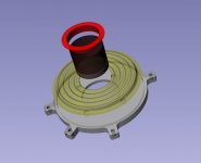
Hello, I need a advice please....
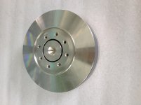
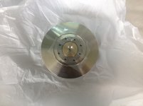
I couldn't wait so I started with a 100 mm mangetic system from a monacor SPH 165C unit.
Would you make the exciter with one or two spiders. Two spider will provide a more stable motion and reduce the rocking movement of the voice coil, but it will increase the weight. Please see picture.
I couldn't wait so I started with a 100 mm mangetic system from a monacor SPH 165C unit.
Would you make the exciter with one or two spiders. Two spider will provide a more stable motion and reduce the rocking movement of the voice coil, but it will increase the weight. Please see picture.
Attachments
I love the 2 spiders designHello, I need a advice please....
I couldn't wait so I started with a 100 mm mangetic system from a monacor SPH 165C unit.
Would you make the exciter with one or two spiders. Two spider will provide a more stable motion and reduce the rocking movement of the voice coil, but it will increase the weight. Please see picture.
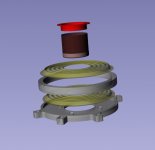
FOR ME, weight is negligible compared to the air resistance of the panel and the power of restitution of the material (of the panel). For stability, I suggest more than an inch separation between spiders. google translator.
Now I have printed the first part and a quick mock-up, just for show. I think that I will do the two spider version to decrease the rocking motion in the system just to bee sure. So I have to do some more drawings and printing.
Take care
Take care
Attachments
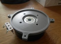
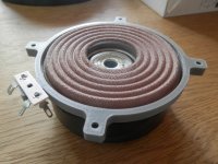
Now I have printed the first part and a quick mock-up, just for show. I think that I will do the two spider version to decrease the rocking motion in the system just to bee sure. So I have to do some more drawings and printing.
Take care
Isn't it nice to have a 3d printer? Which printer do you use and what software are you controlling the printer with? I like your solid fill - looks very smooth. Is that ABS or PLA?
Nice work!

Hi xrk971,
Yes it is soooo nice to have a 3D printer, I bought it to make tools for assembling my speaker units, but now I use it for almost everything.... If I can draw it I can have it. Some of the best money I ever spend.
I got a witbox 3D printer and print with PLA only, due to the toxic gasses from ABS. For slicer I use Slic3r and Cura, for printing I use Cura, Pronterface and some times Witbox own (USB stick)
There is a good reason why 3d printers are called "Santa Claus Machines"🙂
I use Simply3d software - truly plug and play for printer. I did not have to mess with anything to get a first print.
I use Simply3d software - truly plug and play for printer. I did not have to mess with anything to get a first print.
Sub-project: DIY balanced mode radiator (BMR)
Like many of you, I do my "research" in ways similar to the famous joke about the cold-war-era Soviet inventor Regus Patoff ... 🙂
To learn a bit of how a BMR works, I found this patent:
https://www.google.com/search?tbo=p...ode+radiator"&hl=en&tbs=sbdo:1,ptss:a&tbm=pts
Not much just on the search of the basic term, but Graham Banks's idea would seem easy to make from a standard driver. Use the existing cone as the "auxiliar coupler". You'd need to add a "bobbin" to extend the voice coil to drive the center of the panel. Panel will be about 1/3 greater diameter than cone. Existing cone is removed from basket. Additional mounting is needed for panel (or is it? Can it be free-floating?)
This would seem an easy project except for re-doing the basket/mounting. Or we could just buy real BMR from PartsExpress for <$20 each 🙄
In other news, Soldermizer has done further experiments with his favorite adhesive Gorilla Glue. It is possible to thin it with solvents (e.g. xylene) and it also makes a passabe Polyurethane Varnish, however it can only be "water-based" for about one hour 🙂
What happens if...
...we just fasten a flat panel (or disc) to a regular full-range driver? We still have the center "bobbin" driver (a la xrk971's puck idea...) and we just leave the existing cone attached to the default surround but still connect it at the special radius of the disc? The edges of the disc are free.
Obviously this changes the resonant behavior of the disc (does it?) I don't have the modeling software to explore this, but it would surely be much easier to mod existing drivers...
What is the down side of BMR or DML?
OK, at least regards BMR, I have read a spate of patents and manufacterer's promotions of like equipment. I did not realize that these had been a commercial and/or DIY product for five or ten years. Why was I not informed earlier 🙂
A bit of skepticism: if this is so great, then why hasn't it been more widely adopted, especially in the DIY area? Many of the BMR drivers and/or patent documents claim a frequency response of 100 Hz up to bat screams, surely this is Something Wonderful? If they are so easy to make why aren't we creating counterfiets in our cellars 24 hours a day
What is the downside? Too much patent protection?
Like others in this and related threads, I am intrigued by DML and how easy to make one is. Why not try the same with a BMR which is sort of a runt first cousin
Perhaps a simple way to BMR a stock driver
This may be a very simple method to fashion a Bank type BMR:
https://docs.google.com/viewer?url=patentimages.storage.googleapis.com/pdfs/US20130301866.pdf
1. Carefully cut out the existing cone at both ends and throw it away. [Maybe not -- see 1B.]
[1B] Only cut around the top (surround); then you will carefully cut away the top portion of the cone until you have it properly sized for the "auxiliary cone".]
2. Cut a round disc of flat panel material that will connect at surround like a conventional cone.
3. Obtain "bobbin" or "puck" (element that drives from voice coil to center of panel). Install it.
4. (Hardest part?) fashion the "auxiliary cone" that will mount at the 1st mode diameter on the panel. Install it. [4B: figure a way to extend the reduced stock cone so that it contacts the panel in the right area.]
5. Done.
With my previous idea, I was hoping to keep the original cone, but I can't envision any way to get the basket out of the way without cutting metal.
Last edited:
Goin' legit
 It's been too quiet for a week here. Having destroyed or maimed if my memory serves, two CTS "Bose 901" drivers (hapless BMR experimentee), 4 autosound drivers (kinda, sorta work, but repeated pull offs and re-glues are taking their toll...) and hours of tinkering have driven me to [cue ominous music]
Buy a pair of legitimate Dayton (Parts Express) exciters!!!
The Polluto II's are no more (they were the test bed of the BMR abortion) but I did salvage the speaker wire.
I await developments on the "skilled" DIY makers of exciters (ahem!)
I think I will just make a more modest pair of panels the will hang on (or near) the wall and provide what these panels do best -- nice room filling music and can be disguised as paintings or prints with wires trailing out the sides 🙄
In other news, Soldermizer has finally purchased a stud finder, will surely look better than twenty "it must be here somewhere" holes in the ceiling, to mount his green goat skull.
It's been too quiet for a week here. Having destroyed or maimed if my memory serves, two CTS "Bose 901" drivers (hapless BMR experimentee), 4 autosound drivers (kinda, sorta work, but repeated pull offs and re-glues are taking their toll...) and hours of tinkering have driven me to [cue ominous music]Buy a pair of legitimate Dayton (Parts Express) exciters!!!
The Polluto II's are no more (they were the test bed of the BMR abortion) but I did salvage the speaker wire.
I await developments on the "skilled" DIY makers of exciters (ahem!)
I think I will just make a more modest pair of panels the will hang on (or near) the wall and provide what these panels do best -- nice room filling music and can be disguised as paintings or prints with wires trailing out the sides 🙄
In other news, Soldermizer has finally purchased a stud finder, will surely look better than twenty "it must be here somewhere" holes in the ceiling, to mount his green goat skull.
- Home
- Loudspeakers
- Full Range
- A Study of DMLs as a Full Range Speaker