And there are all sorts of "strange" interpretations of DMLs in patents.

From the same patent holder...
From the same patent holder...
It seems like a good summary indeed. As I was saying, the tests would be endless, and this makes the task titanic and perhaps, just perhaps, unsolvable. Essentially, achieving a high qualitative standard seems unattainable. Sure, it solves some problems of traditional speakers, but it creates others that are truly impossible, or at least extremely difficult to solve. And then, if you think about it, if Tectonic has essentially failed, we must ask ourselves if the cause isn’t just bias. Perhaps the limit is insurmountable. Don’t take it the wrong way, it’s just my thoughts out loudDenny Mayer 4 years ago...
Denny Mayer 5 months ago,
Tectonics seems to be defunct; the chap is still around with a new company, but using the same speaker, and with stuffing at the back. The other chap, known for hanging-the-panels-by-strings, still seemed to be active about a year ago. A new chap seems to be active, at least on his website and on YouTube. However, no one is leaving any comments on his videos. A product from a well-known manufacturer is being discussed by a Frenchman. The intriguing fact is that there seem to be no visitors. Excerpts from a six-year-old patent (valid until 2038), now assigned to a German automotive company shown here, take it or leave it. You can bet that people are trying, but the interest in DMLs is in its final throes.
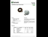
Well, considering the "exciter," it is merely a standard speaker driver, but without the cone and the basket, and featuring a much stiffer spider. The concept of transmitting sound through a panel with tiny holes has been around for a long time. There have also been some patents related to it, though I can't recall which ones at the moment. Some of those ideas are utilised by established speaker manufacturers, without disclosing the reasons for their presence.

Hello Eric,Christian,
Sorry but I am having a hard time following this description. Can you try to clarify?
Eric
Let me try.
Following the first set of directivity measurements which were -90/90° in my first paper, I made a second set with I hope better settings. So prepared (maybe too quickly) a kind of turn table (see picture below) in order to have a fixed axle for the source, a fixed position of the mic and no room reflections before 5ms.
With this set up I tested different sources. Some DML test panels, a wide range speaker (Visaton FRS8 in a small closed box, on the picture), another FRS8 on an open baffle of the same size than the DML (about 30x40cm).
The goal was to have new evidence of the coincidence frequency for material like a 2mm plywood (done, it confirms the fc increases when the thickness decreases with the attention to have in the 2 directions - along and across the grain, for orthotropic materials). It was also to try to see in which way a DML with an open back is similar to an open baffle and to check what are the modifications with different rear load like an absorber, a partially open plate, a closed back.
So for a DML withe suspension, frame, spine and for the FRS8 in open baffle I tested with those different rear load options.
As expected some lobes due to the front and rear waves combination in the 1k to 3kHz range disappeared... Probably as Sandasnikaren suggested other reflections appeared.
My current difficulty is a peak around 500Hz remained what ever the back load is, even a closed one. It is in the measurements of the DML and the FRS8 in open baffle even when the back is closed suggesting the source is not the rear wave. It is not in the measurement of the small closed box.
Thinking more about it, I wonder if it is not simply a reflection from the small "table" supporting the source?
Anyway, as I just saw a similar peak in the FR from Sandasnikaren, I have asked about a possible source.
I hope it is clearer now. Tell me
Christian
Hello Pixel1It seems like a good summary indeed. As I was saying, the tests would be endless, and this makes the task titanic and perhaps, just perhaps, unsolvable. Essentially, achieving a high qualitative standard seems unattainable. Sure, it solves some problems of traditional speakers, but it creates others that are truly impossible, or at least extremely difficult to solve. And then, if you think about it, if Tectonic has essentially failed, we must ask ourselves if the cause isn’t just bias. Perhaps the limit is insurmountable. Don’t take it the wrong way, it’s just my thoughts out loud
As you have experimented DML, it might be interesting that you summarized what points seem to you unsolvable or what are the problems created by DML. Eric has already given some elements about the bandwidth. Even if the 100Hz to 200Hz range is not clear for me, I agree the highs are reachable in not too bad conditions. Sorry if you have already posted that.
Christian
And many too short sentences... Why not to explain what is strange for you in this? For sure there are things to say about the architecture with the cone on the back but it belongs to the familly of DML that tries to supply the bass with a woofer using the flat membrane in that rangeAnd there are all sorts of "strange" interpretations of DMLs in patents.
View attachment 1393502
From the same patent holder...
Christian
The word "strange" was in quotation marks... That patent was from the same "German" company, which is actually Chinese. None of this is strange to me. I've encountered something of this nature in a US patent from the 1950s by a chap named Rich or something similar.Why not to explain what is strange for you in this?
My considerations are not the result of my poor tests, but rather a summary of what I have read in this endless discussion, for which I have great respect, to be clear. My goal was, and still is, a system for professional use, so in addition to quality, overall power is also essential, without which it’s useless. I started with the most obvious thing, trying to replicate Tectonic. I repeat, I’ve never heard Tectonic, but thinking about it, I told myself, ‘if they sell it, it must work.’ Maybe it works, maybe even professional users are skeptical. In fact, after many years, if they have abandoned and never seriously promoted the product, one must wonder if they themselves had doubts about its quality. Wanting to attribute the reasons to something else, though unknown to me, I tried to replicate with a 4mm Nomex material and 0.5mm carbon skins on each side, for a total of about 5mm and dimensions of 60cm x 40cm. The results are not bad at all, but the issues are mostly noticeable at high frequencies. Things improve at high power, but what worries me more is the fact that after over 600 pages on this forum, everything remains unchanged from the first page, still with the same problems. It’s pointless to go over the reasons—you all know them—the membrane material is the issue. There doesn’t seem to be a perfect combination. Everything that could have been tried has been tried. Maybe it exists, but I believe no one has found the right combination; otherwise, these systems would be in use everywhere. Sure, we can continue forever, but it’s not realistic.Hello Pixel1
As you have experimented DML, it might be interesting that you summarized what points seem to you unsolvable or what are the problems created by DML. Eric has already given some elements about the bandwidth. Even if the 100Hz to 200Hz range is not clear for me, I agree the highs are reachable in not too bad conditions. Sorry if you have already posted that.
Christian
lekha,In my Youtube video, there is an option for subtitles. I don't know German too.
Thank you! I did not realize you could "auto generate" a translation in any language. Maybe those Russian videos will be more interesting now!
Eric
No doubt. But Gobel isn't one of them. 😉The concept of transmitting sound through a panel with tiny holes has been around for a long time. There have also been some patents related to it, though I can't recall which ones at the moment. Some of those ideas are utilised by established speaker manufacturers, without disclosing the reasons for their presence.
Christian,My current difficulty is a peak around 500Hz remained what ever the back load is, even a closed one. It is in the measurements of the DML and the FRS8 in open baffle even when the back is closed suggesting the source is not the rear wave. It is not in the measurement of the small closed box.
Thinking more about it, I wonder if it is not simply a reflection from the small "table" supporting the source?
Anyway, as I just saw a similar peak in the FR from Sandasnikaren, I have asked about a possible source.
I hope it is clearer now. Tell me
Yes, much clearer now.
I see you discovered the same as I did that you need to be careful how close your speaker is to the front edge of the table, so that it doesn't fall to the ground when you rotate it! But the problem then is that you introduce a reflection from the table.
Just yesterday I was measuring some of my panels from the back. I had really not done that much before. Most of my high aspect ratio panels have quite deep frames (4-6 inches), so there are also reflections from the inside of the frames that make the impulse response look terrible from backside.
Your observation about the 500 Hz peak is interesting. But I really can't think of a reason why the table reflection would cause a reflection at a particular frequency. I'm sure you are thinking about it already, but you could try to fashion a smaller table that could rotate along with the speaker, so as not to introduce the new reflection surface. It would probably be a better way of creating your directivity plots too.
Eric
Here’s a video from this year's Russian Hi-End exhibition. It is quite lengthy. The reporter moves from room to room, starting on the top floor, inquiring about what the exhibitors have on offer. He is familiar with some of the exhibitors, while others are new to him. Everyone is eager to respond, as it is, after all, free advertising. On one of the floors, he enters one of the rooms and poses the same question. The three rather glum-looking individuals in that room do not reply, so he leaves, somewhat taken aback. That room was virtually devoid of visitors, whereas all the other rooms were bustling with activity. It is a lengthy video, but it is intriguing, as it provides a glimpse of what is available on the other side of the world, a place we will not be visiting for a long, long time.
No subtitles available.
My first intention was first to have a well defined axis. There is a 6mm wood pin in the "table" and so a hole in loudspeaker. Previously, they were suspended to a transformed floor lamp based but it was not easy to change the angle.Christian,
Yes, much clearer now.
I see you discovered the same as I did that you need to be careful how close your speaker is to the front edge of the table, so that it doesn't fall to the ground when you rotate it! But the problem then is that you introduce a reflection from the table.
It might be this frame helps in the bass extension by increasing the delay of the rear wave. It is similar to a U shape open baffle. The risk then (according to what we can read) is a "cavity noise". In open baffle domain, some designer increase the dimension on only one side keeping the other on as short as possible. It is something I think to test. On consequence is the direction ot the null is not at 90° on the wing side.Just yesterday I was measuring some of my panels from the back. I had really not done that much before. Most of my high aspect ratio panels have quite deep frames (4-6 inches), so there are also reflections from the inside of the frames that make the impulse response look terrible from backside.
Yes it is in my intention to make a support without the table effect. Something like a classical loudspeaker stand with the rotation close to the floor and screws to secure the panelYour observation about the 500 Hz peak is interesting. But I really can't think of a reason why the table reflection would cause a reflection at a particular frequency. I'm sure you are thinking about it already, but you could try to fashion a smaller table that could rotate along with the speaker, so as not to introduce the new reflection surface. It would probably be a better way of creating your directivity plots too.
Eric
The peak is much less visible for the FRS8 in a closed box and also with the canvas panel I have tested... but it seems here, hiden in the small peaks and dips of the FR, not coming as the
I will test also a better mic support using a 20mm pipe in addition to increase the distance mic/mic stand.
Christian
I have not figured out the reason for the peak at 480Hz . My assumtion is that some kind of resonance maybe related to the fs of the exciter I’m using. It’s fs is 230Hz +/- 10% and the high peak is at roughly twice that.Hello Scandasnickaren,
Your post is fully on what I consider at the moment!
In this post, are you refering to the panel 250x190mm in post #12529 ? extract below.
View attachment 1393129
I initiated directivity measurements few posts ago mainly to detect possible important lobes at high angles. An update of my last paper should come if I am not going to be lost in new ideas...
From that I think I can conclude that some directivity singularities are detectable quite easily (currently with a gated IR). The need or the way to correct them seems to be an other story (see you post + the general position among the DIYer to use fully open back DML).
The singularities in directivity that are detectable are the lobes due to the coincidence frequency (if the fc is not out of the frequency range) and lobes in the mids that might be the combinaition of the front and back rear in the 40° / 60° range in front.
I observe 2 other singularities which might be with more effects.
One on-axis which is a peak around 500Hz. Going back to your post, I see you have a peak in this range. My test panels are 30x400mm measured at 1m so maybe no relation. Have you found a source of this peak? To be more explicit on why I am scratching my head: I have to explain that I made a set of measurements of 30x40cm DML with different back load, a 8cm large range in an open baffle of same dimension and the same model in a small closed box. The peak is here for the DML and the open baffle with or without a back load (even if it is less with) but not (or very small) with the small closed box. A difference being the front face of the closed box is maybe 10x12cm (and 10cm depth 1.2l).
View attachment 1393136
The second singularity is an important emission around 2kHz to the back of the panel. Have you already observed that?
Going further in my last directivity measurements today, I agree it could be according to what you tested that some rear loads with fast and strong impedance change bring other problems, the balance probably depending of the distance to the front wall.
Christian
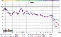
I have measured the directivity att 0, 15, 30 , 45, 60 and 90 degres angles. I’ve done it with and without equalisation.
The spectogram is 0 and 30 degres for the equalised case.
Thomas
Attachments
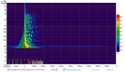
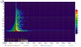
Thank you Thomas,I have not figured out the reason for the peak at 480Hz . My assumtion is that some kind of resonance maybe related to the fs of the exciter I’m using. It’s fs is 230Hz +/- 10% and the high peak is at roughly twice that.
I have measured the directivity att 0, 15, 30 , 45, 60 and 90 degres angles. I’ve done it with and without equalisation.
The spectogram is 0 and 30 degres for the equalised case.
Thomas
Is there a woofer or a sub playing in those FR?
I have also in my hypothesis some resonance related to the exciter characteristics. I don't think it is in direct relation with the fs in the spac. This fs measured with no plate. The plate, depending of the frequency, the mode, shows to the exciter a mass, a stiffness and a damping so a new resonant system is created. At least it is how I see it.
Christian
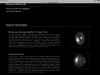
The perforated panel in fig 6 is not the dml panel itself, but a kind "acoustic lens"/helmholtz resonator (?) mounted close behind the panel.As with most reviews, whether paid or otherwise, what is shown is not always what is meant to be seen, often accompanied by some misdirections.
Anyway, One can always give them a ring and ask. The contact details are available in Tefra Audio website.
Whatever balsa he used doesn't really matter; what is important is the holes at regular intervals (fig. 6 of his patent) — "shows a perforated grid plate, preferably made of medium-density fibre material, which has openings of a certain diameter and predefined hole spacing, and which is positioned at a specific distance from the panel." All patents have misdirections. The holes are in the panel itself, not at a specific distance from the panel.
"a certain diameter and predefined hole spacing"... There is no further mention of them anywhere else.
The holes in the panel are quite common (as described earlier) when using vacuum infusion. For foam/glass infusion you can get pre drilled foam.
The perforated panel in fig 6 is not the dml panel itself, but a kind "acoustic lens"/helmholtz resonator (?) mounted close behind the panel.
The holes in the panel are quite common (as described earlier) when using vacuum infusion. For foam/glass infusion you can get pre drilled foam.
The "inventors" never include everything in their patents and almost always omit or miswrite something. It is not in their best interest for everyone to easily copy their "inventions," particularly when it concerns a working or profitable patent for the inventor. It was blocked until October 2022, and by that time, Oliver Göbel had outgrown its use and opened a more lucrative business. It is the same with those Russian and Austrian patents... misdirection. When we read a patent, we must have an open mind and some understanding of the subject, and we should never take it at face value.
Last edited:
No, there is no sub woofer.Thank you Thomas,
Is there a woofer or a sub playing in those FR?
I have also in my hypothesis some resonance related to the exciter characteristics. I don't think it is in direct relation with the fs in the spac. This fs measured with no plate. The plate, depending of the frequency, the mode, shows to the exciter a mass, a stiffness and a damping so a new resonant system is created. At least it is how I see it.
Christian
I’m planning to do three test after the weekend:
1 ) same membrane/panel but with another exciter dayton to se if there are any differences
2) new 3d printed panel with the aspect ratio 0.93 (200x185) using the tectonic exciter 3d printed with the same parameters
3) new panel textreme carbon fibre 0.15mm skins and a 2 mm balsa core with cross grain using the tectonic exciter the aspect ratio will depend on the previous tests. I’m making the balsa core myself in my woodshop.
All test will be done using a open back heavy frame and EPDM .
And I will measure 180 degres i.e. 360.
Thomas
Last edited:
Really?The "inventors" never include everything in their patents and almost always omit or miswrite something. It is not in their best interest for everyone to easily copy their "inventions," particularly when it concerns a working or profitable patent for the inventor. It was blocked until October 2022, and by that time, Oliver Göbel had outgrown its use and opened a more lucrative business.
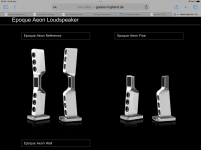
From Goebel high end website.
He is still using his Bending wave technology. Both in a flat configuration and a cone variant.
Thomas
Attachments
Nice to see this thread active again.
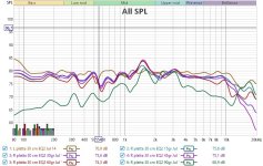
I was doing a quick test today with a different sub and noticed something that others may have already seen. I was trying out measurements at different distances and noticed that the peaks at 0.5m and 1m had smoothed considerably by 4m. They are in room measurements taken quickly and not scientific.
Might explain why panels with sharp peaks can still sound surprisingly good.
Different distances close.

0.5m vs 4m Psy smoothing


Seperated


I was doing a quick test today with a different sub and noticed something that others may have already seen. I was trying out measurements at different distances and noticed that the peaks at 0.5m and 1m had smoothed considerably by 4m. They are in room measurements taken quickly and not scientific.
Might explain why panels with sharp peaks can still sound surprisingly good.
Different distances close.
0.5m vs 4m Psy smoothing
Seperated
When an inventor writes a patent application, he does so because he does not want someone else to replicate his idea—especially if that product is visible, can be dismantled, and copied, etc.—and/or to earn money by granting licences. Only the licensee would receive more detailed information about the patent and would be bound by a very stringent business contract not to disclose the "extra" information.
When one produces the product themselves, only the members or employees of their firm are restricted by a non-disclosure agreement. Oliver Göbel has/had his own production facility, as do the Russians. NXT, who initiated the whole venture, never manufactured any products; they only sold the licence. Tectonics, who acquired the NXT patent rights, have also ceased production. Denny Mayer has a new company—most likely holding the patent rights—but how long it will last remains to be seen.
Among many inventors who did not contest a lawsuit regarding their patent but instead chose to teach their idea at a university, and also transferred their rights to their co-workers when they established a new company, was Edward Villchur. He was, more or less, the father of the "standard" cone speaker.
The thing is, when an idea blossoms in one person's mind, it can be passed on to someone else, but that person's mind cannot be transferred, even if one employs all the power of language. In other words, one can attempt to extract something coherent from someone else's patent and replicate its ideas, but one would never fully know what that "inventor" had in mind. In a patent, the "inventor" reveals just enough information to meet the patent requirements and secure approval. But, of course, everyone has the right to speculate.
- Home
- Loudspeakers
- Full Range
- A Study of DMLs as a Full Range Speaker