Thank you Thomas.No, there is no sub woofer.
I’m planning to do three test after the weekend:
1 ) same membrane/panel but with another exciter dayton to se if there are any differences
2) new 3d printed panel with the aspect ratio 0.93 (200x185) using the tectonic exciter 3d printed with the same parameters
3) new panel textreme carbon fibre 0.15mm skins and a 2 mm balsa core with cross grain using the tectonic exciter the aspect ratio will depend on the previous tests. I’m making the balsa core myself in my woodshop.
All test will be done using a open back heavy frame and EPDM .
And I will measure 180 degres i.e. 360.
Thomas
If you go to directivity measurements, with a material like the CF/balsa core, try to make at least 0/90° measurements according to the horizontal and vertical axis. Eric (@Veleric ) made such tests (I should maybe speed up to post them in an update of my last paper) that show an important difference in the coincidence frequency according to the axis. Something like 15kHz along the balsa grain and "only" 5.8kHz across the grain. The hypothesis is a limited shear modulus in one direction. The consequence being the lobes at the coincidence frequency and above, it is maybe better it happens in a vertical plan.
Anyway, if you want help for the directivity plot from the REW file, let me know, here or by PM.
I recommend also the thread (@Monteverdi ) improving bending wave drivers which is very close to what we discuss here. Many information about motor, coil, membrane.
Christian
Hello Jozka,Nice to see this thread active again.
I was doing a quick test today with a different sub and noticed something that others may have already seen. I was trying out measurements at different distances and noticed that the peaks at 0.5m and 1m had smoothed considerably by 4m. They are in room measurements taken quickly and not scientific.
Yes it is nice. I agree and with real experiences sharing. Thank you for your measurements. I don't think there is a "scientific" question. Any measurement (with a minimum of serious) is better than nothing. We do all measurements at home so with some limitations. What is important is to keep that in mind and try to understand where we reach the limitations.
Your measurements bring a new observation of a peak in the 500Hz range with a new clue which is the influence of the distance (to be confirmed of course that it is the same for Thomas and I).
Focusing on the directivity measurements, I have probably forgotten the influence of the distance in the DML FR.
Christian

Thomas,All test will be done using a open back heavy frame and EPDM .
In the "heavy frame" idea, have you thought to use sand or other heavy powder?
Long time ago, I visited a lab making acoustic measurements in a standard room; all the pipes like the heating system were enclosed in boxes filled with sand.
In the past, there were also loudspeaker enclosures made of 2 thin walls with sand in between. For enclosures, the technique of constrained layer is maybe more efficient in the attenuation to weight ratio.
It is an idea I have for DML frames using PVC pipes or maybe other solutions. As you print in 3D, it may open to possibilities.
I have this topic in mind because in may last tests, I closed the back of a DML with a simple 8mm plywood sheet (about 30x40cm). The emission from this board in the 180° was not negligible. This doesn't say it is audible...
Christian
It would be quite refreshing if someone were to present a new idea, rather than attempting to replicate the somewhat unclear concepts found in existing patents. Oliver Göbel, for instance, has never provided more information than what is available on his website, and that information is rather dated. The only updates on his site pertain to exhibitions where his company or their partners showcase large speakers, but without the DML component. The last time he mentioned the DML component was in 2018, six years ago. Since then, the focus has been solely on large speakers that utilise conventional drivers, whether cone or otherwise.Really?
From Goebel high end website.
He is still using his Bending wave technology. Both in a flat configuration and a cone variant.
Thomas
Certainly, the aim is to achieve good, clear sound from flat panels. The concept of suspending them from strings has been around for a long time, demonstrating the principles of pistonic motion. Similarly, flat panels suspended in frames—both with and without back panels, as well as those with stuffed backs or artistically cut designs on the rear—have also been explored. Additionally, there is a Serbian/Swiss individual promoting the smallest DML panel ever created. The flattened coil glued to the flat panel, with a magnet system positioned just a few millimetres away is also around. However, none of these innovations have gained significant traction yet, not even the Göbel panels or the Russian variants.
NXT has been defunct for quite some time, and its successor, Tectonic, has also shut its doors. The Russians may manage to persist for a few more years, as they are quite resilient, no one in the local community seems interested in copying them anyway. As for the Serbian/Swiss individual, perhaps they could succeed if they learned to sell at commodity prices.
Last edited:
Hej,n the "heavy frame" idea, have you thought to use sand or other heavy powder?
Long time ago, I visited a lab making acoustic measurements in a standard room; all the pipes like the heating system were enclosed in boxes filled with sand.
In the past, there were also loudspeaker enclosures made of 2 thin walls with sand in between. For enclosures, the technique of constrained layer is maybe more efficient in the attenuation to weight ratio.
It is an idea I have for DML frames using PVC pipes or maybe other solutions. As you print in 3D, it may open to possibilities.
I have this topic in mind because in may last tests, I closed the back of a DML with a simple 8mm plywood sheet (about 30x40cm). The emission from this board in the 180° was not negligible. This doesn't say it is audible...
Christian
I used ”plaster of paris” in these frames. It was the easest way to fill them as printed them in two halves. I’m using sand in another concept I’m working on, more on that later.
I’m also considering to use ”epoxy-granite” which have some very intresting characteristics. It’s very often used in machinery to control vibrations. There is a lot to read on the webb if you are curious.
Thomas
For those who may be interested in what Oliver Göbel thought 22 years ago about his panel membrane, here it is.
Yes, I can do a measurement in the vertical axis. However I do not foresee a difference as its cross grain balsa so it’s pretty uniform in both direction. It’s an easy measurement so I’ll do to be sure.Thank you Thomas.
If you go to directivity measurements, with a material like the CF/balsa core, try to make at least 0/90° measurements according to the horizontal and vertical axis. Eric (@Veleric ) made such tests (I should maybe speed up to post them in an update of my last paper) that show an important difference in the coincidence frequency according to the axis. Something like 15kHz along the balsa grain and "only" 5.8kHz across the grain. The hypothesis is a limited shear modulus in one direction. The consequence being the lobes at the coincidence frequency and above, it is maybe better it happens in a vertical plan.
Anyway, if you want help for the directivity plot from the REW file, let me know, here or by PM.
I recommend also the thread (@Monteverdi ) improving bending wave drivers which is very close to what we discuss here. Many information about motor, coil, membrane.
Christian
Yes some info on directivity plot would helpfull, thanks!
Yes, I’ve seen Monteverdis thread, thanks!
Thomas
If people still recall the BMR (Balanced Mode Radiator) drivers, one might ponder what could occur if the cone of a standard speaker driver were to be flattened. Would that flattened cone (of a BMR) be regarded as a distributed mode membrane? Would those flattened cones, when connected to standard drivers, still require enclosures to contain the "rear wave"? Or should a reflex tube with a turbine inside be employed to enhance the bass output?
Is cross grain balsa a kind of balsa plywood? With layers in perpendicular directions? So different from what Eric did and also different from the end grain (Goebel or Monteverdi)?However I do not foresee a difference as its cross grain balsa so it’s pretty uniform in both direction.
Christian
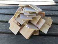
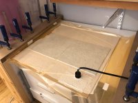
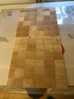
Homemade diy…the result is much stiffer compared to using balsasheets. The thicknes is 2mm after gluing and sanding.Is cross grain balsa a kind of balsa plywood? With layers in perpendicular directions? So different from what Eric did and also different from the end grain (Goebel or Monteverdi)?
Thomas
Attachments
Thomas,3) new panel textreme carbon fibre 0.15mm skins and a 2 mm balsa core with cross grain using the tectonic exciter the aspect ratio will depend on the previous tests. I’m making the balsa core myself in my woodshop.
When you say "cross grain" do you mean the same as "end grain"? Like in these photos (but obviously thinner).


A few weeks ago I made a little test panel with Textreme F-1122. At 100 gsm it sounds similar to what you have. Which grade/model of Textreme is yours? Is it the same?


Eric
Ah, yes, it is end grain. Would love to hear more about your process. Epoxy, just on the edges? What density do you end up at?Homemade diy…the result is much stiffer compared to using balsasheets. The thicknes is 2mm after gluing and sanding.
Thomas
Thanks,
Eric
It’s similar different supplier 88g/sqm.Thomas,
When you say "cross grain" do you mean the same as "end grain"? Like in these photos (but obviously thinner).
View attachment 1394157View attachment 1394158
A few weeks ago I made a little test panel with Textreme F-1122. At 100 gsm it sounds similar to what you have. Which grade/model of Textreme is yours? Is it the same?
View attachment 1394168 View attachment 1394169
Eric
I’ve tried to minimize the amount of epoxy that I use, still room for improvment….
Thomas
This is why I always measure near field and far field.Nice to see this thread active again.
I was doing a quick test today with a different sub and noticed something that others may have already seen. I was trying out measurements at different distances and noticed that the peaks at 0.5m and 1m had smoothed considerably by 4m. They are in room measurements taken quickly and not scientific.
Might explain why panels with sharp peaks can still sound surprisingly good.
Different distances close.
View attachment 1393913
0.5m vs 4m Psy smoothing
View attachment 1393912View attachment 1393912View attachment 1393913
Seperated
View attachment 1393914
View attachment 1393912View attachment 1393913View attachment 1393914
Not much point having a fantastic near field measurement if the far field measurement is bad.
Although a great room response is is the general goal.
Different panel materials, size and shapes will alter the frequency plots.
When testing a new type of panel, I always have to start from scratch again .
trying to duplicate the same measurements of someone else's panel will be impossible unless you have an exact copy of that panel.
Having a panel that measures well does not necessarily mean it will sound good.
This is why I prefer to find materials that sound good rather than trying to build materials that could possibly sound good, but most probably won't.
Steve.
Quite a few years ago, they showcased a pair of thin, painted (and possibly treated) rectangular EPS sheets held in two places by simple soft pads, and people gathered around to listen. At that time, who would want to purchase an "acoustic system" at exorbitant prices when one could simply walk into any hardware store and buy EPS sheets? Everyone could see how the EPS sheets were secured and what was on them—any child could replicate them in a matter of minutes. Therefore, they had to be concealed in a box. Additionally, one had to move away from the readily available EPS sheets.

Consequently, everything was concealed in a box and connected with oddly shaped (and expensive?) wires, yet... no one appeared particularly interested. People, of course, peered in, having paid for tickets, but they wouldn’t stay to listen. Amusingly, instead of suspending the sheets from strings, one could simply secure them through soft pads in just two places—one at the top and one at the bottom, centred in the middle vertically. And one could even glue nice pictures over them—surely, the wife wouldn’t complain!
No unsightly box, but one still has to position them somewhat away from the back wall. It is pleasant to hear the panels in an open corridor, but it could be quite different in a room.
When I went to the Ascot audio show, I was eagerly looking for the Goebel room to see his bending wave panel.Really?
From Goebel high end website.
He is still using his Bending wave technology. Both in a flat configuration and a cone variant.
Thomas
Their room had one ginormous gold plated speaker In the centre of their room.
The first thing I said was, that is not a bending wave speaker.
They pronounced that it was based on bending wave technology 😳.
I asked, in what way ?
No coherent answer was offered.
obviously they didn't have a clue.
They invited me to a demonstration of the monstrosity at some special time and place.
I said I had come to hear the bending wave panels.
Not stare at a 7ft gold monolith.
I left very disappointed 😞.
Steve.
Quite a few years ago, they showcased a pair of thin, painted (and possibly treated) rectangular EPS sheets held in two places by simple soft pads, and people gathered around to listen. At that time, who would want to purchase an "acoustic system" at exorbitant prices when one could simply walk into any hardware store and buy EPS sheets? Everyone could see how the EPS sheets were secured and what was on them—any child could replicate them in a matter of minutes. Therefore, they had to be concealed in a box. Additionally, one had to move away from the readily available EPS sheets.
Lekha, Who is the "they" you are referring to? Göbel? Are you of the opinion that there is no significant sonic benefits of much more expensive, complex materials/configurations for DML panels, compared with what they were showing?
Last edited:
Not Göbel, the Russians...

A quite a long time ago ...
Money is better off staying in your own pockets...
A quite a long time ago ...
Money is better off staying in your own pockets...
- Home
- Loudspeakers
- Full Range
- A Study of DMLs as a Full Range Speaker