The exciter fell off of the round fluted proplex.
The picture shows the soft mounting tape, with its overhang on both sides, which i was not happy about.
You can see the tape sagging.
so I have decided to use this on a small thin wood panel I have been waiting to try.
I think I might compare this to a BMR my friend has lent me(only about a year ago ,🙄 better late than never) only if it measures OK, that is ?
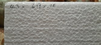
I am not yet going to try the new eps , but here are a couple of pictures of the surface of the material and size in cm.
Steve.
The picture shows the soft mounting tape, with its overhang on both sides, which i was not happy about.
You can see the tape sagging.
so I have decided to use this on a small thin wood panel I have been waiting to try.
I think I might compare this to a BMR my friend has lent me(only about a year ago ,🙄 better late than never) only if it measures OK, that is ?
I am not yet going to try the new eps , but here are a couple of pictures of the surface of the material and size in cm.
Steve.
Attachments


could you share what the actual density is of the EPS foam that you are using please?I am using a HD EPS 500/320mm in size.
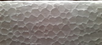
Hello Steve there is quite a difference in the density of those two samples judging by the size of the ball size of the foam as seen in your two photos. The first sample shown looks to be about three times as dense as the second sample. Does this visual assessment match up with a physical evaluation? The smaller the degree of expansion the higher the density.
Nice! Glad to hear the coating worked out for you as well.Thanks for the coating tips Leob, I made a couple of panels in a similar style to yours with the front and back of the panel supported in 6 places with closed cell foam. I uses Hide glue and Shellec as suggested and wow they are the best I've made/heard. Only one exciter each at present but the frequency response is so much smoother and highs much better than my previous PVA coating. I am using a HD EPS 500/320mm in size. The Exciter is a dayton 25fhe at the 3/5 2/5 location.
At first I measured and there was a steep drop off from 300HZ down but lots of highs. I gave them a sand front and back and now measure nicely down to 100HZ ish before they drop off. I must have coated with too much Shellac and they were too stiff.
This is in room away from walls and floor no EQ and 1/6 smoothing. Pretty happy with the results and sound.
View attachment 1290818
Making sure the schellack is thin enough is very important, and it is amazing how so little can make such a big difference.
since shellac is so easy to thin and it dries so quickly (goes on cured) you could apply very light coats and listen in short order and repeat if necessary until you are happy with the sound. If your last coat seems too much then you only have one light thin coat to sand off.Making sure the schellack is thin enough is very important, and it is amazing how so little can make such a big difference.
Has anybody here tried Elmer's Probond Advanced on EPS foam? It would seem to be very good. Have asked Elmer's for more info such as how to dilute etc..
You only need a single coat for sure. The question is how much you dilute and how you apply it. I use 4:1 spirits to shellack and apply with a lacquer brush.since shellac is so easy to thin and it dries so quickly (goes on cured) you could apply very light coats and listen in short order and repeat if necessary until you are happy with the sound. If your last coat seems too much then you only have one light thin coat to sand off.
Not sure how similar it is to your typical transparent all purpose glue, but usually they seems like some kind of plastic?Has anybody here tried Elmer's Probond Advanced on EPS foam? It would seem to be very good. Have asked Elmer's for more info such as how to dilute etc..
Probably a bit similar to epoxy, but doesn't become as hard. And same problems with diluting.
I'm a bit sceptical. Even if you manage to dilute it will become more like a plastic outer layer than a tight skin like with PVA or hide glue.
Moray James.
Sorry , the last picture is a close up macro photo, of the surface.
But yes the the beads tend to get smaller the higher the density.
Steve.
Sorry , the last picture is a close up macro photo, of the surface.
But yes the the beads tend to get smaller the higher the density.
Steve.
me too so I have requested technical data sheet/ We will see what they send and I will post then. I have watched some videos and it looked to be a much stronger bond than Titebond ll pva adhesive and is water resistant. Sounds like a modified pva we will see.I'm a bit sceptical.
Hi Christian,Hello Joska,
Nice FR!
Could you tell us a bit more about your panels (sorry if it is in posts before, for now I check time to time this thread...)?
Thank you
- do you know more precisely the EPS density?
- from which thickness do you start (300Hz version) and what is the final one (100Hz version) ?
- you mention a suspension in 6 points. Could you remind their locations? This might be in Loeb's posts but you know how it is easy to go back to information in this thread.
- how the exciter is glued to the panel (original 3M, PVA, epoxy, other...)?
Christian
I hadn't posted about these ones before so no need to search.
-Eps is VH grade 28kg/m3 20mm thick 500/320mm. I got a sheet from a local packaging/building supply plastics place.
-It was the same panel that only played above 300Hz after too thick a coating of shellac, I gave it a quick sand with the orbital both sides and then it played lower.
- suspension 2 each long side approx 100mm in from corner, 1 middle of short side. I made a frame 19w/40dmm from ply, I left it 19/6mm approx at the front face then cut out the back so it is like an L. The panel is spaced out from the front by 6x 20/8mm pieces of closed cell foam, then a strip around the back edge is screwed on to allow more closed cell blocks to sandwich the panel between. Hope this makes sense, I'll take a photo. Leob's mounting as you can move the blocks/suspension to tune.
- The exciter is glued on with epoxy.
Attachments
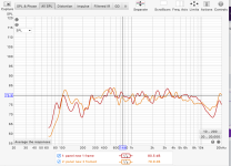
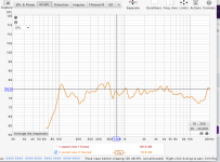
Sorry I am new to REW and haven't figured out how to scale easily, I'll have a look.That's almost 130db in total on the Y axis...
Show us what it looks like from 60db to 120db?
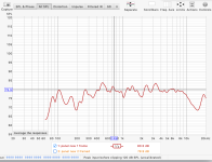
Andre, here are the zoomed FR graphs, slightly less impressive but mostly 5db swings. The orange is the panel I posted and red is the the second panel I made, difference is probably the amount of coating I sanded off. Also the the Red exciter is brand new so maybe needs to break in a little to loosen the suspension?
Attachments
Sorry I am new to REW and haven't figured out how to scale easily, I'll have a look.
Hi JozkaNZ,Andre, here are the zoomed FR graphs, slightly less impressive but mostly 5db swings. The orange is the panel I posted and red is the the second panel I made, difference is probably the amount of coating I sanded off. Also the the Red exciter is brand new so maybe needs to break in a little to loosen the suspension?
Nice results. Is one of these the one that you said only played above 300 Hz?
Eric
@JoskaNZ very nice results, thank you for sharing. Your distortion values are very low compared to what mine have been and the FR is pretty well controlled compared to many of my tests. I'd love to see some pics of your frame and mounts.
You said you sanded the panel and that extended LF. The sanding could well be the cause, but I've also found with all my testing that remounting a panel can make a pretty big change too. These panels are very sensitive to the way they are mounted, and the driver too if it is braced, and remounting it can make small changes to how pressure is applied and this can have a large effect. One of my latest panel experiments is extremely rigid fiberglassed EPS and it gives the deepest LF of all my tests. I think rigidity is required to control the power at LF.
Your peak around 18khz is interesting. I suspect it might come from your driver, and the driver could be limiting the LF a bit too. I've only got the DAEX32EP-4 and I believe it is known to give stronger LF but weaker HF. I don't know much about voice coil engineering but I've been wondering if there's a better way to make a full range exciter since it seems like there's a lot of compromises made here. I think the Xcite driver is better than these Dayton exciters, based on results others have shared.
I had an opportunity to quickly do a loud test today with one of my panels and after just 1 minute of run time at ~95dB at 100hz my driver started smelling and feeling quite warm 🤔 I also had a lot of noise from my duct tape surround flapping...
One thing I've been trying to accomplish with panel experiments is to reduce the deviation from average of not-smoothed frequency response. I want the FR to look less peaky. When comparing say 1/48 smoothed SPL of a test on top of a 1/6 smoothed graph I want them to look as similar as possible. I believe (but am not certain) that the more similar the 1/48 looks to the 1/6 the better the FR will sound. Generally the fewer phase rotations there are the more even the FR will be. Distortion is very important too but I think driver and panel mounts play the biggest role here, as long as the panel material itself isn't noisy.
Impulse Response, Group Delay and RT60 are also important, though more challenging to measure because of room response. I stopped measuring panels very close (which is needed to reduce the impact of the room) because that doesn't accurately represent the listening experience of a DML panel. I got some really good clean smooth results a couple inches away from some panels which don't sound nearly that good at 6ft away. I don't even do 3ft measurements anymore because that's too close for DML imo. A nice smooth reading at 2 inches becomes a lot more peaky and humpy at 6ft because, I think, the sum of the whole panel responds very differently than the few inches of it that dominates the close measurement.
I've done a lot of tests with a very low budget in a poor testing environment and basically just as a hobby. An obsession, really, just exploring different things on a whim as I feel like it without any serious controls or notes with my experiments. What I think I've found though, for whatever it's worth, is that thinner panels tend to produce more stable frequency response (meaning 1/48 more closely matched 1/6) and more rigidity is needed to flatten the overall FR curve and handle power. Lighter weight is needed for better transient response, and then damping is needed to prevent ringing. Wider panels tend to have more 'uncontrolled' FR going on while taller ones give the needed LR.
So I'm liking the taller aspect ratio right now with thin rigid panels, but I'm still working on the mounts and damping. Epoxy on foam certainly does ring. Even bare XPS and EPS ring. One of these days I'll look more closely at acrylic panels because of Valeric's damping measurements.
- Home
- Loudspeakers
- Full Range
- A Study of DMLs as a Full Range Speaker