Nice, clean and simple Eric! What configuration did you use for the 2 exciters on a panel? And from your listening is it bass or treble shy?
The other pics will show the exciter locations, once I get them to load. Don't understand why they don't!


The parts
 [/url]IMG_4470 by ekragness1, on Flickr[/IMG]
 [/url]IMG_4472 by ekragness1, on Flickr[/IMG]
 [/url]IMG_4471 by ekragness1, on Flickr[/IMG]
 [/url]IMG_4473 by ekragness1, on Flickr[/IMG]
 [/url]IMG_4483 by ekragness1, on Flickr[/IMG]
Very nice work! Beautiful.

Btw, these are very low profile almost like you mean to hang them on a wall. Will you fill the back with fiberglass stuffing or similar and hang on a wall? That’s some pretty plywood for “underlayment” ply not meant to see the light of day. What is the wood used - looks almost like zebra wood or bamboo once finished. I think boiled linseed oil might be really good for this as it penetrates and hardens the wood like plastic binder in matrix of lignin fibers.
Btw, these are very low profile almost like you mean to hang them on a wall. Will you fill the back with fiberglass stuffing or similar and hang on a wall? That’s some pretty plywood for “underlayment” ply not meant to see the light of day. What is the wood used - looks almost like zebra wood or bamboo once finished. I think boiled linseed oil might be really good for this as it penetrates and hardens the wood like plastic binder in matrix of lignin fibers.
Last edited:
Very nice work! Beautiful.
Btw, these are very low profile almost like you mean to hang them on a wall. Will you fill the back with fiberglass stuffing or similar and hang on a wall? That’s some pretty plywood for “underlayment” ply not meant to see the light of day. What is the wood used - looks almost like zebra wood or bamboo once finished. I think boiled linseed oil might be really good for this as it penetrates and hardens the wood like plastic binder in matrix of lignin fibers.
Thanks to you (and BurntCoil) for the kind words. Actually I have not thought much at all about how they would be mounted. I consider them mainly an experiment. I suppose I should have thought a little more about that....
The plywood material is called "Revolution Ply" that I bought at Home Depot for about $14 for a 4'x8' sheet.
Sustainable Wood Source Plywood | RevolutionPly
I chose it because of the nice appearance, it's light weight, and because it's 5 ply and hence shouldn't warp as easily as 3 ply stuff. I don't know why they put such a decent looking veneer on the face (and back!). However, on both faces the veneer is very, very, thin. I'd guess it's less than 10 mils thick. I don't actually know what species are used in the veneer or core, but it's as light as anything else I've been able to find. The same company has a product called "SurePly" that is very similar.
I applied Minwax "natural" stain and 3 light coats of Formby's Tung Oil Finish on the face of each panel. I was wary of adding too much weight to the panels, so didn't lay it in very thick.
Eric
I agree on the wall mount option. From my limited experience you could wall mount these if you add some loudspeaker stuffing to the rear of the panel. Just one layer, uncompressed, applied to the rear surface would work. That would work well inside your frame depth. Then you could use your nice frames as the mounting point.
Your options on stand mounting are numerous as you know. Those frames give you a lot of options.
Your options on stand mounting are numerous as you know. Those frames give you a lot of options.
Nice, clean and simple Eric! What configuration did you use for the 2 exciters on a panel? And from your listening is it bass or treble shy?
geosand,
The exciters are both at about 0.47 along the long side and at 0.3 and 0.44 across the short side. I determined these locations by experiment. For simplicity of construction I wanted to support both on the same spline so that's the main reason they are both along the 0.47 line. But I played around with other more random locations and no other pair of locations complimented each other any better than this one so I went with it.
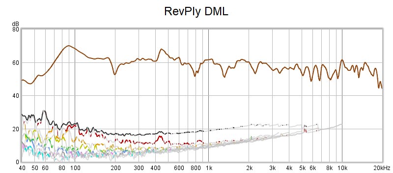
Here's an REW measurement I got last night. Distortion is about 0.5% over most of the range. There is a blip of distortion at around 450 Hz that grows when I turn the volume up. I will have to see if I can figure out how to clean that up.

I agree on the wall mount option....
Your options on stand mounting are numerous as you know. Those frames give you a lot of options.
Considering the WAF, there are few (if any) options!
Mine shut me in the loft.Considering the WAF, there are few (if any) options!
Interesting plot, should get a great performance.
Thanks sharing build Veleric,
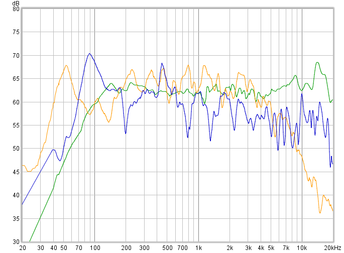
Interesting it looks you get a relative good HF reach there, below 50dB vertical scale comparison should give some feel of response to other systems, blue graph is yours from post 848, orange graph is xrk971 dual exciter from post 1, and green graph is factory datasheet a generic 3 inch wide band transducer Tymphany TC9.

Interesting it looks you get a relative good HF reach there, below 50dB vertical scale comparison should give some feel of response to other systems, blue graph is yours from post 848, orange graph is xrk971 dual exciter from post 1, and green graph is factory datasheet a generic 3 inch wide band transducer Tymphany TC9.
Attachments

Hi Eric, thank you for sharing your build and knowledge here. This is a facinating thread and I am struggling to keep up and make notes. Nice to see some framed panels and yes - it is such a simple and neat implementation. I am still undecided about frames for my first planned build one day. A couple of things I find interesting regarding your build and questions that came up in my mind. You don’t have to answer them all.I finally decided to actually make a pair of DML's. I've been playing around for months with different panel materials, sizes, exciters, frames and splines, but still didn't have a pair to just sit and listen to. I realized that I was getting into analysis paralysis, so decided it was okay just to build something, even if it was far from optimized. So I did.
1) At 16 x 23 inches your panels are relatively small for DML panels, yet it looks like you are getting a very decent frequency range here. Could it be because you have two exciters per panel? Is it necessary for two exciters on such relatively small panels?
2) The way you mounted the exciters on the spline. Actually they don’t look like they are fixed (like rigid with screws) to the spline, but merely wedged between the spline and panel with EPDM foam.
3) I have limited understand of the REW plots, but it looks like you are getting very good HF here. Could this perhaps be because the exciters are sort of mounted to the spline and frame, and therefore have more control in exciting the panel especially for the high frequencies? It looks like X noted better sounding highs after he added moulding clay to his exciters which gives more weight behind them, which might give them better control in exciting the panels.
4) You are using two 4 ohm exciters – are they connected in series?
5) Why are the corners not rounded?
6) I see other speakers in the background with what looks like MA 10.3 drivers – how do the panels compare to your other speakers at this stage?
I want to get some of those panels at HD. They look way too good to be just underlayment only. The trick is getting that home. Might have to ask them to cut it in store. 4x8 ft is huge. That respond eindeed goes very high and reaching 100Hz is perfect to fill in with a subwoofer.
1) At 16 x 23 inches your panels are relatively small for DML panels, yet it looks like you are getting a very decent frequency range here. Could it be because you have two exciters per panel? Is it necessary for two exciters on such relatively small panels?
This size is actually a copy (not exact, but close) of a Tectonic DML-10. I started working with this size before I had any idea of how size influenced performance. But based on my current calculations, it's actually a pretty reasonable size for this plywood, or PS foam, or gatorboard, and probably others. And by that I mean it's large enough to be capable of decent output around 100 Hz or below.
I don't think that multiple exciters does anything to extend the frequency range. I used two in this build for several reasons. Mainly, because plywood has relatively low efficiency, and needs two exciters for decent volume, probably regardless of the panel size. A single exciter on PS foam is still louder than two on plywood. A second reason for two exciters is because both my amps want 6-8 ohms resistance. Finally, using a second exciter can help fill in dips in the frequency response of the first exciter, if placed in good spot (if you can find it!).
2) The way you mounted the exciters on the spline. Actually they don’t look like they are fixed (like rigid with screws) to the spline, but merely wedged between the spline and panel with EPDM foam.
You are almost right. True, no screws, but also not wedged. The EPDM foam is taped to both the spline and the exciters. I felt these exciters needed the spline for support, but I feared that a truly rigid support would be even worse than no support at all, if for example, the panel or spline warped a little bit over time. I don't know if this approach is unusual or not. I once noticed that the JMC Soundboard DML appears to have the exciters mounted on a suspension of sorts, but I could be mistaken.
3) I have limited understand of the REW plots, but it looks like you are getting very good HF here.
I only know I get better HF extension with plywood than other panels. I have no explanation for why. I don't think it's the spline, because I see similar response without it.
Yes.4) You are using two 4 ohm exciters – are they connected in series?
5) Why are the corners not rounded?
Because it was easier not to, and I'm not at all convinced it does anything beneficial.
6) I see other speakers in the background with what looks like MA 10.3 drivers – how do the panels compare to your other speakers at this stage?
Yes, those are my MLTLs. Honestly I have purposely avoided a direct comparison so far! The MLTLs go down to about 40 Hz, so don't need subwoofer assist. The DMLs definitely need the sub. But other than that, I think the DMLs do pretty well.
Thanks sharing build Veleric,
Interesting it looks you get a relative good HF reach there, below 50dB vertical scale comparison should give some feel of response to other systems, blue graph is yours from post 848, orange graph is xrk971 dual exciter from post 1, and green graph is factory datasheet a generic 3 inch wide band transducer Tymphany TC9.
BRYTT,
Very cool overlay! Funny, mine has dips where ever xrk971's has spike, and vice versa. Combine them for dead flat response!
Eric
BRYTT,
Very cool overlay! Funny, mine has dips where ever xrk971's has spike, and vice versa. Combine them for dead flat response!
Eric
And thats exactly what the Tech Ingredient guys did in their second video, They combined the outputs of acoustic ceiling tile with XPS to get a better, smoother output in the far field. There claim was that was far superior to using weights for damping of resonances. But talk about lack of WAF and the amount of space needed...it works, but is it practical for anyone?
BRYTT,
Very cool overlay! Funny, mine has dips where ever xrk971's has spike, and vice versa. Combine them for dead flat response!
Eric
Had not noticed that good spottet 🙂
Find it interesting that many down the thread report of higher resolution from their builds compared to normal speakers, as was the case pages back replaying the Lou Reed track Walk on the wild side over DML panel, aware non controlled subjective review reports can be misleading but in that many talk resolution imagine there must be something about it.
Thinking over why the reported higher resolution made me do the overlay, you know find differences to normal speakers because responses so far looks not be very smooth and maybe that non smooth distortion can subjective be interpreted as a higher resolution is a thought, other differences to normal speakers could be if these panels are true omni including their HF reach which if they are would bring them closer to how most natural instruments works, and also xrk971 impedance plot from post 1 show interesting stuff, know it looks scary ragged but overall impedance swing in ohms is actual only a small fraction compared to normal transducers and should lead to less phase distortion when we use voltage amps to feed a current device.
About response think it would be interesting if some dips are someway more or less destructive or they can simply use a 100% reverse mirror EQ and panel system then goes flat as a rock or to whatever the target curve wish is set at.
Have best fun thame 450Hz point 🙂
Last edited:
Have best fun thame 450Hz point 🙂
Thanks for your encouragement (haha). A guy needs to have dreams, right?
- Home
- Loudspeakers
- Full Range
- A Study of DMLs as a Full Range Speaker