If you've tried to read that Karavashkin thesis, even with translation, it is Chinese to most of us. So, a question arises, how could a Swiss guy read that in Russian and actually understood that? 🙂Interesting. Thanks for pointing that out. When I said that the "transverse gas wave" concept was not mentioned in the Herger patent, I was referring to this one (filed 6/2020):
https://patents.google.com/patent/RU2743892C1/en
which still does not mention it as far as I can tell. But as you point out, indeed it is mentioned in this other one filed just two months later:
https://patents.google.com/patent/RU2744773C1/en
Curiously, the two patents describe pretty much the same exact features, but only the second one mentions the significance of the "Karavashkin transverse gas waves". Patent strategy can be confusion, but I have to wonder if they figured it would be unlikely to be granted in the US or Europe in the original form, but then somebody had the idea to toss in the Karavashkin "thesis". Regardless of how dubious the thesis is, they thought it might be worth a shot.
Eric
I can read technical papers in a few Slav languages, but that Karavashkin "science" stumped me.
Last edited:
Re is 7.1 ohm.2 good points in this spec : the resistance (7Ohms) and the inductance (0.05mH) compare to more usual 4 Ohm, 0.1mH at the best so the current and then the force will be maintained further in the frequency range. BL is good not excellent
Good also to have holes at the top of the voice coil to allow the air escaping hopefully with no or little noise.
yes BL is 4.8. But, I’m using 6 exciters so its 28.8.
I thought I'd read all I can find of Henry Azima's work, as he is the person, who coined the term Distribution Mode (DM) and Distribution Mode Loudspeaker (DML), as though I had never read any of his work before, that is with a clean slate. I also don't want to "colour'' my mind by reading other people's patents in the meantime. Henry Azima was an immigrant from Iran, which I learned, just a few moments ago. Sometime ago, I read "NXT When a Little Chaos is Good For You." That actually prompted me to read further.
Well, I made some notes on his thoughts from that article. I changed acronym NXT to DML, where I thought appropriate, that is for easy understanding. It is still in his own words.
------------------------------------------------------------------
Well, I made some notes on his thoughts from that article. I changed acronym NXT to DML, where I thought appropriate, that is for easy understanding. It is still in his own words.
------------------------------------------------------------------
- But conventional listening rooms are far from anechoic, so a loudspeaker's output off the listening axis has a significant effect on what we hear.
- Each small area of the panel vibrates, in effect, independently of its neighbours.
- But how can you make a diaphragm vibrate randomly? Actually, you can't, but you can get very close to it by using what we term distributed mode (DM) operation.
- The diaphragm of a Distributed-Mode Loudspeaker (DML) vibrates in a complex pattern over its entire surface. Close to the diaphragm the sound field created by this complex pattern of vibration is complex also, but a short distance away it takes on the far-field characteristics of the DML radiation. This is close to the directivity of a true point source - i.e., approaching omnidirectionality - even when the diaphragm is quite large relative to the radiated wavelength.
- The radiated sound is dispersed evenly in all directions. Diffuse radiation of high order becomes omnidirectional in the far field.
- Distributed Mode operation guarantees consistent output level and undistorted time response in all directions. In other words, all the radiated energy appears to originate from a single point.
- A DML loudspeaker is insensitive to diaphragm size, the acoustic behaviour (other than sensitivity) is unaffected by diaphragm mass.
- Another major benefit is that the panel's acoustic output from both sides of the DML panel is useful. The power radiated from the back face sums up constructively with radiated power from the front face of the panel. This is due to the complexity of distributed-mode radiation and the uncorrelated phase of the individual radiating elements as seen from the far-field point of view.
- The velocity of sound in air is independent of frequency, whereas the velocity of bending waves in an DML panel is frequency dependent i.e., bending waves are dispersive. The panel vibrations are very small in amplitude, putting much reduced demand on the coil excursion, with the panel remaining well within its linear elastic range.
- The conventional wide dispersion (omnidirectional) loudspeakers produce a large, blurred stereo image rather than the precise, tightly defined sound stage of more directional designs. The stereo imaging of a DML, in typical domestic surroundings, is at least as well defined and stable as with conventional directional loudspeakers listened to from the stereo `sweet spot'. Outside this small area of optimum stereo, the DML panel is much superior because of its better maintained off-axis performance and reduced of room interaction.
- With conventional wide-directivity loudspeakers you also tend to hear much more of the room: standing wave resonances are more pronounced, so the tonal balance varies significantly as you change listening position, and interaction with room boundaries is worsened too, making speaker placement more critical. DML panels behave quite differently because of the diffuse nature of their radiation: their sound does not emanate from a fixed, well-defined point in space. As a result, the distribution of sound within a room is actually much more even with a DML panel than with a conventional loudspeaker: room interaction is reduced.
- Provided you know a few key parameters - the size and shape of the panel (it can be curved in one or more plane), the position of the exciter(s) and the bending stiffness, surface density and internal damping of the panel material - it is possible to predict the acoustic performance with a high degree of accuracy.
- It does away with the audible consequences of crossover networks; its wide, essentially frequency independent directivity removes a pervasive source of coloration; despite this, room interaction is reduced and stereo imaging remains sharp over a large listening area; DML panels are thin and can either be used in free space or wall-mounted, so their footprint and visual impact are reduced; cabinet resonances are no longer an issue because there is no need for a cabinet.
- The unique ability of DML panels to fill a room with a sound field which alters very little as the listener changes position is further enhanced by the reduced fall-off in sound pressure level with distance compared with a conventional loudspeaker.
a question on your question about a rubber puck. Is this what you thinking of?Well, you are going to use them indoors, so the measurements are not the most important matter, but how it sounds to you, and your wife/partner. 🙂
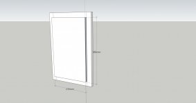
What's interesting is, the transverse waves made by 6 sources at the same time are fighting each other on the same plane and still gives nice output. At what distances, they are placed on the panel? Have you put a rubber puck inside the bobbin/coil-former under the exciter? Do you have the angled lines/cuts on the perimeter of the panel as Gobel's? If so, at what angles, at what distances?
You've left the edges free,
View attachment 1126974 Is it because it acts more like a BMR?
https://patents.google.com/patent/CN201118973Y/en
Thomas,a question on your question about a rubber puck. Is this what you thinking of?
https://patents.google.com/patent/CN201118973Y/en
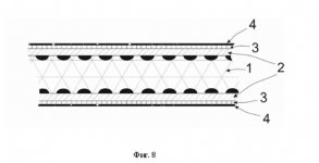
It may or may not be the same thing, but I suspect he was thinking of this (below), which comes from an english translation of the Goebel patent. Since your (early) design was based on the Goebel patent, I suspect chdsl was wondering if you included this feature in your own version.
I will add that it's not actually clear to me what problem it is that this puck feature is intended to solve. If anyone thinks they can explain it, I'd be interested to hear it. I'd like to try it myself, but if I don't know what it is really supposed to do, I won't be able to judge if it works or not.
Eric
It would be handy if someone grouped together all the sound clips of the different panel material's or maybe post numbers.
Maybe they are they saying that the panel under the exciter develops oil-can resonances at hf, which cancels the direct vibrations from outside the perimeter of the exciter at some high frequency. The puck may be designed to damp those inner resonances.Thomas,
It may or may not be the same thing, but I suspect he was thinking of this (below), which comes from an english translation of the Goebel patent. Since your (early) design was based on the Goebel patent, I suspect chdsl was wondering if you included this feature in your own version.
I will add that it's not actually clear to me what problem it is that this puck feature is intended to solve. If anyone thinks they can explain it, I'd be interested to hear it. I'd like to try it myself, but if I don't know what it is really supposed to do, I won't be able to judge if it works or not.
Eric
View attachment 1128063
It is what Valeric mentioned here #8,266. Thanks for the link to the Chinese patent, though. Interesting how Henry Azima's work had inspired the world. Paul Haddock too used that idea to rid the actions of the empty area inside the coil former area, only in a different way. #7,541a question on your question about a rubber puck. Is this what you thinking of?
https://patents.google.com/patent/CN201118973Y/en
In your 6 exciter panel, it is interesting how the surface bending waves fighting each other and still giving out pretty good sound.
I am using Henry Azima's terminology now -- bending waves of the surface of the material. 🙂 You have used angled line cuts on your Gobel clone. Can you give the dimensions and angles and so on on that? Thanks.
Last edited:
Wow, haha, you are right, DPK really does claim that:
View attachment 1127789
I'm skeptical, I must admit.
I hate to risk going down this sketchy rabbit hole any farther, but my curiosity has the better of me. So can anybody translate this figure?
- the Karavashkin papers read like pseudoscience to me. And the SELF laboratory seems sketchy at least.
- I had the impression that the DPK speaker was based on the Herger patent. Is that correct? And if so, whey didn't it mention this hitherto unstudied phenomenon, if it's so basic to the function of this speaker?
Eric
View attachment 1127794
Maybe, this patent might give a hint who should be asked to give us some explanations on DPK_TST?
and,
Разработчик DPK TST >> Developer DPK TST
Its bit strange reading this reply #8,229 now.
Last edited:
Further to post #8,270,
An excerpt from that patent,

and the Google auto-translation,
The proposed loudspeaker is based on the ability to generate a transverse acoustic wave (http://selftrans.narod.ru/v2_1/acoustics/acoustics03/acoustics3rus.html) under the action of resonant excitation by surface-traveling waves that arise on the membrane and form frequency-amplitude centers of opposing oscillations within certain zones on the surface of the sound-emitting membrane. A distinctive feature of this method of sound emission is the formation of a circular sound field around the source, with the properties of a uniform distribution of the frequency balance and amplitude of oscillations in the area of such a field. The degree of signal attenuation becomes inversely proportional to increasing distance (rather than the square of the distance in the case of loudspeakers on conventional speakers). In practice, in the case of built-in acoustics, the radiation pattern is a hemisphere with a source in its center, and the opening angle of the sound beam is 180° with virtually no degradation of the frequency balance and signal amplitude.
-------------------------------------------------------------------------------------
From Danilo Herger patent,

An excerpt from that patent,
and the Google auto-translation,
The proposed loudspeaker is based on the ability to generate a transverse acoustic wave (http://selftrans.narod.ru/v2_1/acoustics/acoustics03/acoustics3rus.html) under the action of resonant excitation by surface-traveling waves that arise on the membrane and form frequency-amplitude centers of opposing oscillations within certain zones on the surface of the sound-emitting membrane. A distinctive feature of this method of sound emission is the formation of a circular sound field around the source, with the properties of a uniform distribution of the frequency balance and amplitude of oscillations in the area of such a field. The degree of signal attenuation becomes inversely proportional to increasing distance (rather than the square of the distance in the case of loudspeakers on conventional speakers). In practice, in the case of built-in acoustics, the radiation pattern is a hemisphere with a source in its center, and the opening angle of the sound beam is 180° with virtually no degradation of the frequency balance and signal amplitude.
-------------------------------------------------------------------------------------
From Danilo Herger patent,
Last edited:
Over the years I have posted on many occasions the problems within the coil surface area and how to deal with them on different panel materials.Thomas,
It may or may not be the same thing, but I suspect he was thinking of this (below), which comes from an english translation of the Goebel patent. Since your (early) design was based on the Goebel patent, I suspect chdsl was wondering if you included this feature in your own version.
I will add that it's not actually clear to me what problem it is that this puck feature is intended to solve. If anyone thinks they can explain it, I'd be interested to hear it. I'd like to try it myself, but if I don't know what it is really supposed to do, I won't be able to judge if it works or not.
Eric
View attachment 1128063
This is the same problem, and this is his way of dealing with them on his panels.
Steve.
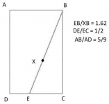
I could not figure out from these patents, the lines BD and BE , which is the preferred line or do you have exciters in both positions?Further to post #8,271,
These images are exactly same in both patents,
View attachment 1128151
and this with another Herger patent,
View attachment 1128152
You might find other similarities, reading those patents, with a translator.
Or do you remove the one from X when using the red line ?
It is as clear as mud.
Steve.
Hello Herb777It would be handy if someone grouped together all the sound clips of the different panel material's or maybe post numbers.
I can offer to add cells in the realization sheets of the history file. I can collect the link of the last sound clips (I mean from the last update point) when I will update the file (when is an other story). For older one, I won't turn again all the page of this long thread so if the owners of the realization listed (or others) want to post again the link, no problem to store it.
Christian
Over on audiocircle you had a picture gallery for all your pictures.It would be handy if someone grouped together all the sound clips of the different panel material's or maybe post numbers.
It would be handy to have something similar here with also music clips.
It made life a lot easier ,to help find things.
Steve.
I have been reading all of these patents (not in Russian) and it has now done my head in !
I must go and lie down now and remind myself not to read them anymore.
I seem to remember a manufacturer using a similar red line on their panels , can't remember who ?
Steve.
I must go and lie down now and remind myself not to read them anymore.
I seem to remember a manufacturer using a similar red line on their panels , can't remember who ?
Steve.
If you read my post #8,270, you'd know who to ask that question. 🙂I could not figure out from these patents, the lines BD and BE , which is the preferred line or do you have exciters in both positions?
Or do you remove the one from X when using the red line ?
It is as clear as mud.
Steve.
It is quite funny the Petrushevski+5 patents match the Danilo Herger patents. Some of the sentences appear to be equal, as though they come from the same computer, the way they are written. And, the images are exactly same.
Last edited:
The only gas waves I understand, is the ones from the large amounts of Brussels sprouts I ate last night with my roast 🤣Steve,
Can you clarify what you believe you now understand but previously didn't? Are you talking about this transverse gas wave concept, or something else?
I do agree that two exciters out of phase would create bending moments, that would be different and perhaps stronger for at least some frequencies than a single exciter. But neither of the Herger patents specify that two exciters are necessary, let alone that when two are used they are run out of phase.
When they talk about "antiphase" components, I read it as referring to this type of thing, which happens in a DML regardless of how many exciters there are:
View attachment 1127911
Are you thinking something different?
Eric
I think you are right, it was me over thinking, because of the vagueness of the patents.
I started thinking of piezoelectric drivers bending the panel with no pistonic motion.
Then started to think how two exiters could mimic the piezoelectric plate.
I put 2 and 2 together and made 5 🤯
I wonder ?
On a side note ,I seem to remember a ply panel that I made which had a far too strong a wave in it, which I had to damp with a wooden beam.
The end flapped so strongly that it was like a fan.
i vaguely remember my attempts at burntcoils tall blondes that I was getting high output from the top of the panel ,when the exciter was at the bottom, the top end was fee to vibrate, the bottom was not.
I think there is something similar to a tuning fork going on here?
Steve.
You are talking in riddles again ?If you read my post #8,270, you'd know who to ask that question. 🙂
If he wished to tell us I'm sure he would have done by now.
Steve.
- Home
- Loudspeakers
- Full Range
- A Study of DMLs as a Full Range Speaker
