
Agree with this, but a simple one transistor reg could be a second option for something really simple discrete design. A good starting point. This 3 trannies and 1 jfet design gives for sure much better measuring results and could be still considered as "simple" discrete design. Loop gain is not as high as it could be with opamp but this one works quite well.One eventually needs to learn to build basic amplifiers, and voltage regulators.
yeah but which ones?
Start with the simplest ones, work your way up. As always.
It really depends on what one needs out of a “voltage regulator”. Does one need .1% load regulation, the option of current limiting, low noise, adjustability? Or does one need to simply break power supply loops to prevent motorboating or drop excess voltage and keep it relatively steady to run op amps or housekeeping circuitry? One will find applications for both if you stay with this long enough.
what do these 3 extra transistors do and how they are better than a simple transistor/zener regulator?Agree with this, but a simple one transistor reg could be a second option for something really simple discrete design. A good starting point. This 3 trannies and 1 jfet design gives for sure much better measuring results and could be still considered as "simple" discrete design. Loop gain is not as high as it could be with opamp but this one works quite well.
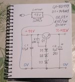
Also Vref is very stable if temperature changes (6.2V zener in series with Q2 Vbe voltage have opposite TC).
And it gives 12.00V at start and keeps it stable at normal room temperature. Have not tested more than 12 hours continuous power on.
And temperatures from +15 Celsius up to +35 Celsius output voltage changes no more than 20mV. All this is measured data. Some drift of course but not big one.
Can also build and measure this simple one transistor+zener reg, but it is not as good. Just think about how it works.
I have to say, I do feel more for the approach where the amplifier design is not so dependent on very well regulated supply voltage.
Make the cap too large and it can fry the pass transistor at turn on or turn off. It’s a dead short at start up, but that’s ok if the surge is short duration (milliseconds). At turn off it could hold a charge after the input collapses and reverse bias the transistor. That’s cured with an inverse parallel 1N4001, pointing from emitter to collector. The regulator itself provides a low output impedance so a large bypass cap is unnecessary. Small ones right at the amp’s output transistors are always a good idea to insure that impedance stays low well into the MHz, where wiring inductances or the regulator’s fT are limiting factors.
Added D4 and R2 to discharge C2 if tested without amp. Reg gives around 12.1V when amp is connected. Q1 needs heatsink, same one like used before.
Regulator with feedback have much better measuring result, but this one is good enough and still simple.
Regulator with feedback have much better measuring result, but this one is good enough and still simple.
Attachments
It's a bit late now, seeing as he has been "baned", but I see nothing wrong with a "try it and hear for yourself" challenge. Never mind setting fire to straw men:@cumbb I think it is nicer if you limit your paraphilic audiophile nonsense to those threads were experienced technicians can assess the absurdity what you usually blabber. And not in threads were inexperienced beginners try to put their first steps in audio electronics.
Things like the case type of a transistor, the amount of solder on a joint or the directivity of copper only make a difference to your ears or imagination. Sometimes I think it is funny to read the fantasies you come up with. But please, post in in the threads were you don't confuse people with less experience.
Orthe amount of solder on a joint
If you could kindly quote those two statements, that would be appreciated. I could only find you claiming that cumbb said it in this thread.the directivity of copper
As for cutting the heat-sinking tab, it's an interesting idea: it would reduce mechanical strain on the silicon, as the tab is allowed to expand and contract evenly in all directions, rather than being constrained by a cold metal loop that causes various bending forces to be applied. You scoff, yet the piezo-electric effect is well-known physical phenomenon. How, or to what extent it could practically affect the sound is an open question, and it's not the first time I've seen people going on the attack because they're somehow offended by ideas that are indistinguishable from snake oil unless sugar-coated with science-y marketing.
He did not say that in this thread. The amount of solder was in a thread about "restoring" an amplifier. Directivity of copper he has mentioned in other threads. But I don't want to put in the effort to look it up.If you could kindly quote those two statements, that would be appreciated. I could only find you claiming that cumbb said it in this thread.
- Home
- Amplifiers
- Solid State
- A simple discrete one-watt amplifier