Hi friends, strangely after so many years of TAs building we are still wondering about the mysterious forces (SF, SD) that move them; e.g. I naively imagine a car on a curved road with two nice guard rails.
There are three ways to run that curve
A - steering the wheels at the proper angle to keep us in the middle of the road
B - going straight and rub against the outer guard rail
C - steering too much the wheels, until rubbing against the inner guard rail
and there are three types of tone arms
X - a revolutionary arm, with the right offset angle
Y - the linear arms, with zero offset angle
Z - the pivoted arms, with too much offset angle
Everyone can make the analogies he likes, and draw the necessary conclusions. Naturally by evaluating the friction on the constraints, the points of application of the forces and relative favorable/unfavorable levers: much better with a simple vectors breakdown
carlo ;-)
(Surely cars are pushed by the engine, while TAs are pulled by the SD, surely the car runs on the steady road, while the TA stands still on the moving disc... )
I forgot: my car has a servo steering, but it's me the one who drives the car
Attachments
Further thoughts about the skating force.
What is the skating force? Let’s look at the classical definition by James Kogen in his article, The Skating-Force Phenomenon.
Friction between the stylus tip and the record produces a force, Ff, tangent to the record groove at the stylus tip. The reaction force of the arm, Fg, must pass through the arm pivot. The two forces Ff and Fg combine as vectors, leaving an unbalanced force, Fs, which is by definition the skating force.

The mechanism to generate skating force consists of many components, i.e., groove, stylus, headshell, arm wand, and arm pivot. All the components are integrated and linked parts to produce a skating force. If you take one component out or break, (or in a fancy word, decoupling), the linkage. You will have the following consequences.
I understand that the force to drive the arm inwards is a combination of skating force and normal spiral groove interaction. I won’t include normal spiral groove interaction here in order to simplify the discussion.
For the purpose of keeping tangential accuracy, a solid headshell can do a much better job than a floating headshell.
What is the skating force? Let’s look at the classical definition by James Kogen in his article, The Skating-Force Phenomenon.
Friction between the stylus tip and the record produces a force, Ff, tangent to the record groove at the stylus tip. The reaction force of the arm, Fg, must pass through the arm pivot. The two forces Ff and Fg combine as vectors, leaving an unbalanced force, Fs, which is by definition the skating force.
The mechanism to generate skating force consists of many components, i.e., groove, stylus, headshell, arm wand, and arm pivot. All the components are integrated and linked parts to produce a skating force. If you take one component out or break, (or in a fancy word, decoupling), the linkage. You will have the following consequences.
- There will be no skating force.
- The arm will be broken down.
- The arm will be motionless.
I understand that the force to drive the arm inwards is a combination of skating force and normal spiral groove interaction. I won’t include normal spiral groove interaction here in order to simplify the discussion.
For the purpose of keeping tangential accuracy, a solid headshell can do a much better job than a floating headshell.
Last edited:
Ralph's headshell is not floating, it is rather servo driven. Or, if you like it better, the arm is servo driven related to the headshell, instead of at the pivot point.
In a traditional tonearm, the skating force acts on the stylus, which is firmly attached to the tonearm through the headshell.Further thoughts about the skating force.
What is the skating force? Let’s look at the classical definition by James Kogen in his article, The Skating-Force Phenomenon.
Friction between the stylus tip and the record produces a force, Ff, tangent to the record groove at the stylus tip. The reaction force of the arm, Fg, must pass through the arm pivot. The two forces Ff and Fg combine as vectors, leaving an unbalanced force, Fs, which is by definition the skating force.
View attachment 1062351
The mechanism to generate skating force consists of many components, i.e., groove, stylus, headshell, arm wand, and arm pivot. All the components are integrated and linked parts to produce a skating force. If you take one component out or break, (or in a fancy word, decoupling), the linkage. You will have the following consequences.
For Ralf’s arm, if you break, or “decouple” the linkage between the headshell and the arm wand, the arm won’t move and there will be no skating force. As I said many times, the interaction of the stylus and the groove is the only source of the force to move the arm. Once you completely break, or “decouple” the linkage between the headshell and the arm, the arm won’t move at all. There will be no force to drive the arm. There will be no reaction force at the pivot, Fg as in Kogen's diagram, so, no skating force.
- There will be no skating force.
- The arm will be broken down.
- The arm will be motionless.
I understand that the force to drive the arm inwards is a combination of skating force and normal spiral groove interaction. I won’t include normal spiral groove interaction here in order to simplify the discussion.
For the purpose of keeping tangential accuracy, a solid headshell can do a much better job than a floating headshell.
In Ralf's arm the skating force acts only on the tonearm but not on the stylus or the headshell, so the expression 'decoupled' is rightly used. The floating headshell only transfers the friction force to the tonearm.
In a traditional tonearm, the skating force acts on the stylus, which is firmly attached to the tonearm through the headshell.
In Ralf's arm the skating force acts only on the tonearm but not on the stylus or the headshell, so the expression 'decoupled' is rightly used. The floating headshell only transfers the friction force to the tonearm.
According to Cambridge English Dictionary
decouple, verb
to separate from someone or something else; to separate something from something else that it was joined to or part of:
So, are you saying that the headshell is separated from the arm? Obviously, it is incorrect. The headshell is still connected with the arm but through a linear rail. There is no decoupling.
Now, the story is getting even better. the linear rail becomes a gatekeeper. It keeps the evil force, the skating force, out of the stylus and headshell, but channels the friction force, ( are you sure that you didn't mean skating force?) to the arm. It is a beautiful story but it is not true.
Hi Jim,
Please consider this:
1 “Self Propelled”
The title of an invention does not make or break an invention. You are welcome to petition the US Patent Office to change the name of my patent to something more to your liking. They actually have a provision for accomplishing that.
2 “A Floating Head Shell”
In reference to attachments 1, 2 and 3, attachment 1 shows a head shell as an integral part of the tone arm with anti skating theoretically exactly correct. The cantilever operates from its perfect center position and everything is as it should be. However, that scenario actually never happens! Instead, the cantilever will always assume a less advantageous position, either to the left or to the right of its ideal position as shown in attachments 2 and 3 respectively. This is due to the fact that, the frictional forces that produce the inward force constantly change because of vinyl composition, frequency and sound level content in the LP’s groove.
If we separate the head shell from the tone arm proper, we prevent the cantilever from being biased by the inward force as shown in attachments 2 and 3. Of course the inward force hasn’t gone away and if we look at attachment 5, we can see that, the head shell is being pulled against the ball bearing at the very front of the cradle. That force against the ball bearing causes the tone arm to be cammed in a clockwise direction. If we don’t control that clockwise motion of the tone arm, the tone arm and the head shell will collide. To prevent that collision, a torque motor is provided to apply a counterclockwise torque to the tone arm to prevent the above mentioned collision.
To keep the head shell approximately centered above the cradle, a Hall Effect sensor is provided and located in the cradle. The Hall Effect sensor is wired to a PCB which in turn operates the torque motor.
The output of the Hall Effect sensor is controlled by a magnet, attached to the head shell and floating (there is that dreaded word again) above the Sensor.
I have allowed the head shell ±.090” of motion on top of the cradle so as not to collide with the cradle. The interaction between the Hall Effect sensor, the PCB and the torque motor, prevent any possible collision between the head shell and the cradle.
I forgot where, but somewhere you questioned my offsetting of the cradle.
Before I designed my tone arm, there was only one reason to offset a tone arm’s head shell and that reason was to provide tangential tracking at the null points of pivoting tone arms. That offset angle is approximately 22°.
When I designed my pivoting and tangentially tracking tone arm, I realized that I would have to move its pivot for horizontal rotation a short distance to make it work. In order to keep that distance as short as possible, the pivot should be moved along a straight line that intersects the center of the turntable platter. For a tone arm of conventional length, that distance is approximately 1.600”. That is how my 1980s tone arm was designed and built.
When I designed and built the tone arm of this thread, I realized that I could reduce that 1.600” distance by 50% if I offset the head shell by approximately 12°, thus reducing the “foot print” of its mounting area.
Attachment 4 shows the tone arm cradle assembly without the head shell. It also shows the cam and cam followers that control the precise path of the tone arm assembly. As you can see, the motion of the tone arm “adds” 23.9° to the playing time of a piece of music which is about 1° less than a conventional tone arm.
Attachment 5 hopefully makes it clear how the various components interact.
The end result is a tone arm that tracks tangentially with zero tracking error and with a head shell/cartridge assembly completely isolated from the negative effect of the inward force.
My tone arm is not servo controlled, but the anti skating force is.
Sincerely,
Ralf
Attachments
Last edited:
Hi Ralf,
Thank you for your post to help me to understand your arm better! However, I can't still agree with what you said.
The arm travels across the surface of the record. Please see the diagram. The path is a red dot line in the diagram.

In theory, the linear rail has a different position at every point, such as A, B, and C so on in my diagram. The green lines in the diagram represent the positions of the linear rail. Since the position of the linear rail is changing constantly, the linear rail is always not in the same direction as the skating force. The skating force will pull the headshell against the front ball bearing, therefore, the arm moves inward. Again, this is the connection. The headshell and arm are two separated parts, but they interact with each other in order to move the arm. Since the direction of the linear rail is always not in the same direction as the skating force, adding a linear rail doesn't help to avoid the negative effect of the skating force on the cantilever.
Furthermore, let me assume that the arm sits on the record at the beginning without any movements. Everything is fine. But once the record starts to move, the groove will apply a force on the stylus. The stylus will pull the arm toward the center. The cantilever will be displaced. So is the headshell. Once the headshell is displaced, it will send a signal through the Hall effect sensor to the torque motor to generate a counter force. When the torque motor starts, the displacement of the cantilever already happened. The process repeats again and again. So, the correction happens after the cantilever is already displaced. The deflection of the cantilever is inevitable for all the arms in record playing back. The question is how much.
Jim
Thank you for your post to help me to understand your arm better! However, I can't still agree with what you said.
This is exactly what I have repeated many times. It doesn't matter what you add on. In your case, a small linear rail, the stylus still has to perform the duty to pull the arm toward the center because the interaction of the stylus and the groove is the only source of force. There is no other way to move the arm except the stylus. Here you said it in your own language. The headshell is being pulled against the ball bearing. This is the connection. How can you say the headshell and the arm are completely separated? Yes. The headshell and arm are two separated parts, but they interact with each other in order to move the arm. Once the headshell is separated from the arm, the force generated by the interaction of the stylus and the groove won't transmit the force through the headshell and then, to the arm.Of course the inward force hasn’t gone away and if we look at attachment 5, we can see that, the head shell is being pulled against the ball bearing at the very front of the cradle.
The arm travels across the surface of the record. Please see the diagram. The path is a red dot line in the diagram.
In theory, the linear rail has a different position at every point, such as A, B, and C so on in my diagram. The green lines in the diagram represent the positions of the linear rail. Since the position of the linear rail is changing constantly, the linear rail is always not in the same direction as the skating force. The skating force will pull the headshell against the front ball bearing, therefore, the arm moves inward. Again, this is the connection. The headshell and arm are two separated parts, but they interact with each other in order to move the arm. Since the direction of the linear rail is always not in the same direction as the skating force, adding a linear rail doesn't help to avoid the negative effect of the skating force on the cantilever.
Furthermore, let me assume that the arm sits on the record at the beginning without any movements. Everything is fine. But once the record starts to move, the groove will apply a force on the stylus. The stylus will pull the arm toward the center. The cantilever will be displaced. So is the headshell. Once the headshell is displaced, it will send a signal through the Hall effect sensor to the torque motor to generate a counter force. When the torque motor starts, the displacement of the cantilever already happened. The process repeats again and again. So, the correction happens after the cantilever is already displaced. The deflection of the cantilever is inevitable for all the arms in record playing back. The question is how much.
Jim
Last edited:
There were couple posts (#2235 & #2368) by Carlo in another thread, per my suggestions, that illustrate some truly passive versions of Ralf's arm, in concept at least. Carlo's long rail is reduced to Ralf's "cradle." Instead of Carlo's parallel straight track, Ralf turned his arm into articulate pivot tangential track. I believe the "decoupling" of the headshell from the cradle is independent "enough" to have zero or next to zero skating force exerted to the cartridge movement.
The definition given fro decoupling would apply to railroad cars, certainly.
I guess there is no such thing as a decoupled counterwieght? All that I have seen are attached to the tonearm.
One should consider there are usually many definitions of a word and over the centuries words which once had a simple meaning are being used to name other things.
I guess there is no such thing as a decoupled counterwieght? All that I have seen are attached to the tonearm.
One should consider there are usually many definitions of a word and over the centuries words which once had a simple meaning are being used to name other things.
DD,
I don't think Carlo's design is the same as Ralf's in principle. But I will let the author himself explain it.
In your mind, Ralf's arm is essentially a small linear arm with a servo to correct the position of the linear rail. I disagree.
Let's assume you are right for a moment and take a look at the following diagram.

In the diagram, the headshell's original position is drawn in black lines. The cantilever is tangential to the groove. No problem here. Now, if the headshell moves along the path of the linear rail, the new position is drawn in green lines. You can see the cantilever is no long tangential to the groove. Clearly, the headshell can't and shouldn't move along the path of the linear rail. In fact, such linear movements don't exist due to the cam system.
Now, let's take look at what is actually happening. Please see the following diagram.

For a tangential pivot arm, such as Ralf's, every point on the path of the stylus has a corresponding point on the cam system, A1 to A2, B1 to B2, and C1 to C2, etc. Once the headshell is driven by the spiral groove inward, the headshell can't move along the linear rail, green lines in my diagram. The correct positions are indicated in the following diagram.

The headshell in black lines is the original position of the headshell. Once the headshell is driven by the groove, the headshell will move along the stylus path. The headshell in red lines is the new position of the headshell. The line rail in a different position is not parallel to each other. Please see the green lines in the diagram. The conclusion is that the headshell on Ralf's arm can't and shouldn't move along the path of the linear rail.
Based on that, my question will be
What function does the linear rail have?
I don't know and can't see the need for a linear rail. This is why I said many times that a linear rail does nothing but causes problems.
I don't think Carlo's design is the same as Ralf's in principle. But I will let the author himself explain it.
In your mind, Ralf's arm is essentially a small linear arm with a servo to correct the position of the linear rail. I disagree.
Let's assume you are right for a moment and take a look at the following diagram.
In the diagram, the headshell's original position is drawn in black lines. The cantilever is tangential to the groove. No problem here. Now, if the headshell moves along the path of the linear rail, the new position is drawn in green lines. You can see the cantilever is no long tangential to the groove. Clearly, the headshell can't and shouldn't move along the path of the linear rail. In fact, such linear movements don't exist due to the cam system.
Now, let's take look at what is actually happening. Please see the following diagram.
For a tangential pivot arm, such as Ralf's, every point on the path of the stylus has a corresponding point on the cam system, A1 to A2, B1 to B2, and C1 to C2, etc. Once the headshell is driven by the spiral groove inward, the headshell can't move along the linear rail, green lines in my diagram. The correct positions are indicated in the following diagram.
The headshell in black lines is the original position of the headshell. Once the headshell is driven by the groove, the headshell will move along the stylus path. The headshell in red lines is the new position of the headshell. The line rail in a different position is not parallel to each other. Please see the green lines in the diagram. The conclusion is that the headshell on Ralf's arm can't and shouldn't move along the path of the linear rail.
Based on that, my question will be
What function does the linear rail have?
I don't know and can't see the need for a linear rail. This is why I said many times that a linear rail does nothing but causes problems.
Headshell is decoupled from horizontal mass and movement of the main arm. Vertical mass and movement do rely on the arm. And that's the whole point of the design. Decoupled does not equate with detached!I guess there is no such thing as a decoupled counterweight? All that I have seen are attached to the tonearm.
Hi Dd;
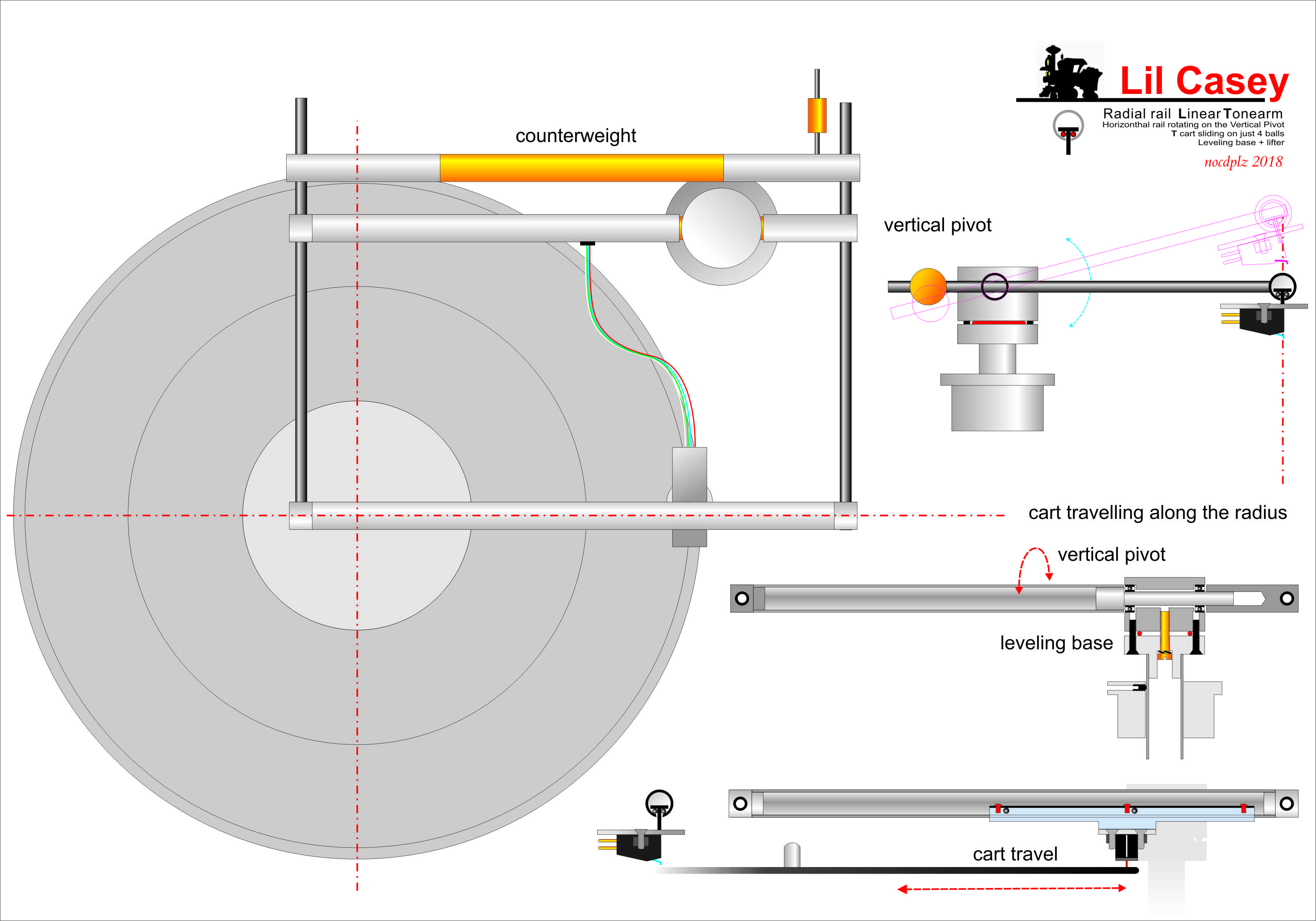
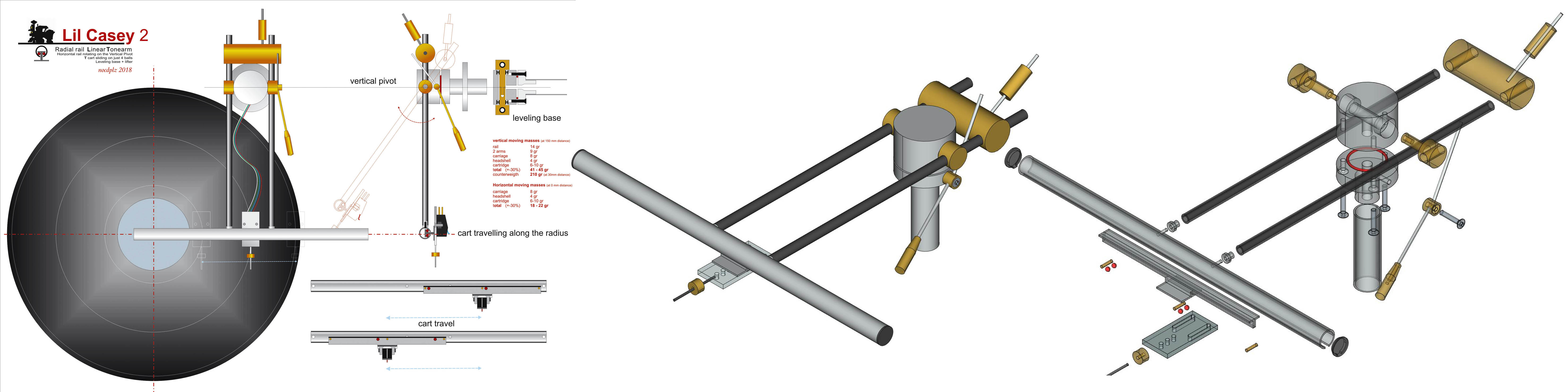
unfortunately for me, the Lil Casey, even in those first rough sketches has very little to do with Ralf's arm. The Lil Casey is just a linear tracker with a new radial rail to eliminate completely the negative lever of the (short!) wand of all the LTAs around. Not a small detail, since that negative lever is a very stupid way to move the carriage.
But that doesn't make it seem a Ralf's arm.
Because the Lil Casey, like all the linear ones, uses only the Side Force (even if much less, without that negative lever) to move the carriage, while Ralf's arm uses only the Stylus Drag and only in the quantity necessary for the head shell movement: for that task a clever PLT geometry allows it to use half the offset of a normal Baerwald PTA. And the stylus drag, being a symmetrical friction, keeps it perfectly aligned to the groove (see my # 241 metaphor, even for the servo topic) the quantity in excess for the floating head shell movement is fully dispersed on the small rail. So nothing left to deal with pivot misalignment.
As for decoupling, I'm Italian and I don't know how Shakespeare would have used that word, but in TAs and TTs sector i've seen used for all structures that are not continuous, not rigidly coupled to the others: decoupled cartridge, decoupled CW decoupled plinth 'n so on, (all questionable practices for a correct resonances path, Imho)
So, in my bad english, that arm is fully decoupled, and selfpropelled too. Again my congrats, Ralf.
carlo
Last edited:
Carlo, I was using the illustrations to show the idea of a widened track of Ralf's arm but I did not intend to equate your carriage system with Ralf's "cradle". The point is that if the cradle is widened to cover the record area, about 4 inches, where the floating headshell traverses strictly horizontally (unlike your carriage that allows some vertical movement) and is so low mass that the only thing to move it is the groove. You use the word "separation" before so we all have the same idea regardless of what word we used. The floating headshell takes care of the horizontal movement and that main arm is for vertical movement and tracking force. As alighiszem once said "The arm itself is driven by the skating force and only the skating force, and the floating headshell is driven only by the groove." Floating headshell and pivot arm are doing their own duties (plus the servo) but also work in harmony to achieve full operation. Using skating force as a mean to activate the servo is a genius touch!
Obviously, Ralf's arm is more elegant with some bonus features that have already been discussed in previous posts.
Jim to this day continues to argue that skating force still exists even with floating headshell that renders unnecessary. To that, I'll let the designer defend his own concept, which I thought he did already. To me, even if it does, it's so minute that's almost non-existent. Ironically, Jim's diy refashioned Birch style Reed 5A tonearm prooved to have little skating force without the need of any counter force mechanism. I don't see Ralf's arm can have more skating force than that type of arm.
In closing, what I learned from Ralf's innovation is that it inspired me to think on separate planes of a tonearm. This design along with Trenton's "Jacob's ladder" bearing tonearm design are the two most innovative concepts in recent years or decades!
Last edited:

DD,Jim to this day continues to argue that skating force still exists even with floating headshell that renders unnecessary. To that, I'll let the designer defend his own concept, which I thought he did already. To me, even if it does, it's so minute that's almost non-existent. Ironically, Jim's diy refashioned Birch style Reed 5A tonearm prooved to have little skating force without the need of any counter force mechanism. I don't see Ralf's arm can have more skating force than that type of arm.
I don't understand why you guys keep saying that Ralf's arm has no skating force. In fact, he purposely introduces the skating force for his arm by adding an offset angle(although I disagree with the need for adding an offset angle. The need for an offset angle may be caused by his particular cam system). The floating headshell, the torque motor, and the term, self-propelled, are all based on the existence of the skating force. If his arm has no skating force, he doesn't need to add a torque motor and floating headshell at all. After adding the torque motor to the arm to counter the skating force, and adding a floating headshell, he thinks the negative effect of the skating force is avoided. I agree with him about the effect of the torque motor. The torque motor is a very clever device. It can be precisely dialed to encounter the skating force. The torque motor also reduces the negative effect of the skating force on the stylus. But I disagree with him about his narrative about the floating headshell because the floating headshell can't only pass the positive force, regular interaction of the stylus and the groove, to the arm and drive the arm, in the meantime, the floating headshell keeps the negative force, the skating force, away from the stylus.
Ralf thinks the floating headshell completely isolates the negative effect of the skating force. I disagree with that. In your late post, you said that it may reduce the negative effect of the skating force to a certain degree. All I want to say is that the floating headshell can't completely isolate the negative effect of the skating force.
For my 5B, I still don't know where is the reaction force for the skating. So, I don't know how to analyze the skating force in theory up to now. However, the skating force tests clearly indicated that my 5B doesn't skate. I thought that my 5B would skate, but the tests proved I was wrong.
For Ralf's arm, its reaction force is clearly defined. His arm may have very little skating force. But the small amount of skating isn't reduced by the floating headshell. It will be nice if Ralf can perform the skating tests like mine. If he can, he may disable the anti-skating device, and do the tests with and without the floating headshell.
Jim
Last edited:
Ralf's pivot arm has skating force but the floating headshell, which is a mini linear tonearm, has no skating force and that was demonstrated in some of his videos. Go watch those again. If it had skating force the headshell would slide right away, exceed the speed of the servo, and hit the cradle!
Bonus: Applying skating force on the swing arm is strategic so he can use a torque motor to counter the skating in order to center the cradle for the baby/floating headshell. Who cares if there's skating force anywhere as long as there isn't any at the cartridge.
Bonus: Applying skating force on the swing arm is strategic so he can use a torque motor to counter the skating in order to center the cradle for the baby/floating headshell. Who cares if there's skating force anywhere as long as there isn't any at the cartridge.
In all the videos I saw, the stylus stayed in the groove. The headshell didn't slide because the groove wall prevented the headshell from sliding. This is why the skating tests must be performed on a blank disk as I and Wally Tool did. If there are other videos I didn't see, please provide me with the links. If he can perform the blank disk tests with the torque motor disabled, I will be happy to admit I was wrong if the headshell doesn't slide.Ralf's pivot arm has skating force but the floating headshell, which is a mini linear tonearm, has no skating force and that was demonstrated in some of his videos. Go watch those again. If it had skating force the headshell would slide right away, exceed the speed of the servo, and hit the cradle!
I already proved that for his arm, the headshell shouldn't move following the linear rail, unless
1. Change the tangential accuracy of the stylus with the groove.
2. Raise the headshell on corners slightly. That may happen in reality.
Last edited:
I did a mental skip jump! You are absolutely right that it should be tested on a blank disc or mirror surface disc like a laserdisc. I look forward to seeing such test. I'm confident it will not skate on a blank disc or laserdisc. Time will tell, if Ralf ever does a test.This is why the skating tests must be performed on a blank disk as I and Wally Tool did.
Ralf, I just wanted to add my respect for your design and your journey. I understand the principles and your design is an elegant embodiment. You should be proud!
Best regards,
Mike
Best regards,
Mike
Duh. I am not the one having trouble with decoupled meaning detachedHeadshell is decoupled from horizontal mass and movement of the main arm. Vertical mass and movement do rely on the arm. And that's the whole point of the design. Decoupled does not equate with detached!
Hi everyone,
I must have missed some of the above posts and I will respond to them when I get the time.
However, the main reason for this post is this:
I am in the process of building two more prototypes of my pivoting tangentially tracking tone arm this year. (2023)
Its operating principle is identical to that of the tone arm described in this thread.
The changes I am making pertain to ease of manufacturing, improved appearance and mechanical simplification.
It will include "on the fly vertical tracking angle adjustment" which my previous tone arm did not have.
I have finished the solid model CAD work and it is ready to be made.
Should I continue with making my new tone arm public in this thread or should I start a new thread?
Sincerely,
Ralf
- Home
- Source & Line
- Analogue Source
- A Revolutionary Pivoting Tangential Tone Arm