Hi Johnmath,But they might be a problem if they generate noise that is coupled into the tonearm.
If a railroad car came barreling down the tracks at 60 mph, everyone would hear it.
If the same railroad car moved down the tracks an inch per hour, nobody would hear it!... I think.
Sincerely,
Ralf
Hi 2wice,What is the purpose of the servo amplifier in the patent?
The servo amplifier drives a voice coil motor which in turn provides a variable force in opposition the the inward force.
Sincerely,
Ralf
Sorry Jim, I'm not following you: what is the force that makes the arms move? I only know S.D. and S.F. Is there anything else around?
Because I still don't understand how the hell linear trackers can move, without using either the S.D. (which is obviously dispersed) or even the S.F. in your description.
What I have observed is that the LTAs inevitably show some cantilever CW bending, (due SF, or what?) often much higher than that CCW of the pivoted (due skating).
Blank disk: quote, but also the SD is different from that of a signal groove
carlo
Thanks Dd - I'm just an old retiree with time to waste. My job was anything but it, and it wasn't just a job.
In the engineering context of a guide following a race, noise is any divergence from perfectly smooth and even motion, particularly at the other end of the tonearm where the effect is magnified by the ratio of the arm length. In the event of an eccentric record the arm may move in and out at a per revolution rate. The bearings on which the cartridge carrier moves will not be perfectly frictionless/noiseless, so some artefacts of roughness or lash in the guide mechanism will be passed through to the cartridge carrier. If we assume that a vinyl record has a dynamic range of 60dB, then very, very small perturbances to the cartridge body (~1/1000 of the groove modulation) can result in noise above the floor of the pickup. Whether your mechanism will cause a measurable or audible effect I have no idea; but to dismiss the existence of said noise offhand flies in the face of physics.
Last edited:
Of course passive linear trackers have the headshell moved by a sideways force generated by the offset of the cantilever from rest position and there is an immutable and consequential tracking error associated with the cantilever offset. Observe the cantilever angle of cartridge on a linear tracking tonearm and that becomes blatantly obvious. Watch how a linear tonearm causes the cantilever to sea-saw wildly with eccentric records. Any stiction in the bearings of the headshell carrier will be manifest, and there is always some degree of stiction, no matter how small.
An active linear tracker can potentially keep the tracking error within a defined limit, provided the sensor / servo / actuator system is well enough designed. In the case of every linear tracking arm I have seen the tracking error corrects in steps, not continuously like a pivoting tonearm. After 50 years of optimising tonearm performance of all sorts of designs I'm not convinced that linear tracking arms are a panacea for anything. The quality of a record player's reproduction is a function of the synergy of all of it's parts, and a tiny element can adversely affect performance.
An active linear tracker can potentially keep the tracking error within a defined limit, provided the sensor / servo / actuator system is well enough designed. In the case of every linear tracking arm I have seen the tracking error corrects in steps, not continuously like a pivoting tonearm. After 50 years of optimising tonearm performance of all sorts of designs I'm not convinced that linear tracking arms are a panacea for anything. The quality of a record player's reproduction is a function of the synergy of all of it's parts, and a tiny element can adversely affect performance.
Personally, following Percy Wilson old attempt, I chase the dream of doing the same on a pivoted one passively, struggling very far from a solution. It will remain a dream, I believe
ciao carlo
I think you are not far from the solution, on the contrary. My simulations show that with variants of your Rabbit high precision can be achieved beside low skating forces. Just two bearings - it can't be simpler .
Attachments
carlo,Sorry Jim, I'm not following you: what is the force that makes the arms move? I only know S.D. and S.F. Is there anything else around?
Because I still don't understand how the hell linear trackers can move, without using either the S.D. (which is obviously dispersed) or even the S.F. in your description.
What I have observed is that the LTAs inevitably show some cantilever CW bending, (due SF, or what?) often much higher than that CCW of the pivoted (due skating).
Blank disk: quote, but also the SD is different from that of a signal groove
carlo
Thanks Dd - I'm just an old retiree with time to waste. My job was anything but it, and it wasn't just a job.
Please see the diagram. I think the diagram itself is sufficient to express my view.
Yes. Linear arm usually has a higher deflection of cantilever due to high friction of linear bearing and high lateral mass. If the friction is almost zero as the pivot arm, and optimal lateral mass, the deflection can be less or similar.
It is different for a stylus in the groove and on a blank disc. However, if the stylus is in the groove, we can't detect visually whether or not there is a skating force. Although there are differences for a stylus in the groove from the stylus on a blank disc, it doesn't affect the conclusion of the blank disc test. We can visually detect if tonearm skates or not.
Jim
Ralf,Hi Jim,
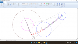
Here is the drawing I promised to explain the origin of the inward force.
Sincerely,
Ralf
I don't question the offset angle will generate an inward force, but I question if it is necessary to add such an additional force.
I used Fushion 360 to redo the geometry of your arm and realized that an offset angle can make the cam simpler. Is that the true reason to add an offset angle? However, it may still be possible to make a simple cam without an offset angle. Otherwise, I really don't see the reason to add inward force since the groove will drive the arm inward. The dot lines are the geometry I did.
Jim
Last edited:
Hi Jim,Ralf,
I don't question the offset angle will generate an inward force, but I question if it is necessary to add such an additional force.
I used Fushion 360 to redo the geometry of your arm and realized that an offset angle can make the cam simpler. Is that the true reason to add an offset angle? However, it may still be possible to make a simple cam without an offset angle. Otherwise, I really don't see the reason to add inward force since the groove will drive the arm inward. The dot lines are the geometry I did.
Jim
View attachment 1019745
1) The pivot of any pivoting tangentially tracking tone arm must move from point A to point B.
2) I have shown that the distance between points A and B is ~50% shorter when the head-shell is offset.
2) A secondary benefit of the offset head-shell is the fact that it drives the tone arm across the LP and all I have to do to prevent the head-shell from colliding with the tone arm, is to provide antiskating.
3) All tone arms with fixed head-shells bend the cantilever because antiskating cannot be set precisely.
4) By separating the Head-shell from the tone arm, it tracks the LP with zero tracking error and without bending the cantilever.
5) My tone arm continues to functions flawlessly and has been listened to and approved by audiophiles.
6) Finally, the Examiner at the US Patent Office who is an Engineer, approved my invention without reservation.
Sincerely,
Ralf
That's clever, it looks like the offset allows the force vector to be parallel to the tangent to elliptical, no wasted energy.
The length is not critical, but efficiency is. I have tried. If the head-shell is not offset, the cam in the rear may be getting complicated. Even with the offset, the cam is not perfect. Please see the following diagram. There is a small bump on the curve. It may cause the stylus jumps. However, I don't think it is important since the stylus is at the end of the groove when the bump happens.2) I have shown that the distance between points A and B is ~50% shorter when the head-shell is offset.
2) A secondary benefit of the offset head-shell is the fact that it drives the tone arm across the LP and all I have to do to prevent the head-shell from colliding with the tone arm, is to provide antiskating.
As I said many times, the only source of the driving force is the friction between the cantilever and the groove. Let's do an experiment. Take your moving head-shell off. Does your arm move? Of course not. The offset angle itself doesn't generate inward force. In other words, taking the head-shell off means the head-shell is completely independent of the arm. If the head-shell is completely independent of the arm, the arm will NOT move at all. All cantilevers on different arms will be bent in different levels based on how efficient the bearing is or the bearings are. So, how efficient the bearings are on your arm? I have doubts but don't know for sure.4) By separating the Head-shell from the tone arm, it tracks the LP with zero tracking error and without bending the cantilever.
Here is a diagram to show the direction of the inward force. The inward force is not parallel to the moving head-shell (blue line) and will pull the arm inward. Why do you need a moving head-shell since the moving head-shell can't be completely independent of the arm? Bending cantilever is inevitable for all tonearms even you add a moving head-shell. The question is how much.
It would be nice if you can run the arm on an eccentric record and record the movements of the cantilever so we can see how efficient the bearings are for your arm.
Jim
Last edited:
Hi everyone,
I am pleased to announce that, I have received a patent from the US Patent Office covering the subject tone arm in this thread.
The title of the patent is: "A FLOATING HEAD SHELL FOR A SELF PROPELLED, TANGENTIALLY TRACKING TONE ARM".
The patent number is: 11,315,598 B2.
Being retired and on a fixed income made it impossible for me to hire a patent attorney and pay thousands of Dollars to obtain a patent. So, I did it myself. I have had a lifelong interest in inventing, Inventors and patent reading. In the 1980s when I received a reasonable salary, I still could not afford to hire a patent attorney and therefore prosecuted my first 1980s patent myself also.
Back then the patent office required that, all patent drawings had to be drawn on 64 ply Bristol board with black India ink.
for some time now it has been allowed to use a CAD program to make the drawings. Luckily I have owned such a program since 1994.
If you have read the above thread, You will know that the subject tone arm of this thread employs a moving pivot.
While I was writing the specifications for my patent application, it occurred to me that the floating head shell would also be of benefit to a conventional pivoting non-tangentially tracking tone arm. So, I made sure that my patent application included text and claims to protect the use of a floating head shell for conventional pivoting tonearms.
In 2021 I manufactured five conventional pivoting tone arms using my floating head shell. They are of Bearwald configuration and have tone arm pivot to turntable pivot distances of 222mm. I was 95% finished, when a devastating computer crash stopped me for about three month. I now have a new computer, and I will be finishing the five tone arms shortly. In a week or two, I will be starting a new thread featuring this tone arm.
Sincerely,
Ralf

The title of the patent is: "A FLOATING HEAD SHELL FOR A SELF PROPELLED, TANGENTIALLY TRACKING TONE ARM".
The patent number is: 11,315,598 B2.
Congratulations, Ralf! So happy to hear your invention getting protection and, hopefully, recognition and financial gain in the future.
Congratulations !Hi everyone,
I am pleased to announce that, I have received a patent from the US Patent Office covering the subject tone arm in this thread.
- Home
- Source & Line
- Analogue Source
- A Revolutionary Pivoting Tangential Tone Arm