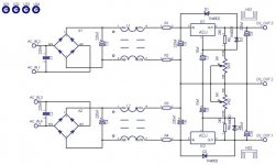
That last schematic looks very much like Russ Whites http://www.twistedpearaudio.com/lcbs/lcbs.aspx
Low Current Bipolar Power Supply (LCBPS) - A Regulated CLRC Supply
Except his has CLRC network on the input now. A very nice reasonable priced kit.
Cheers George
Low Current Bipolar Power Supply (LCBPS) - A Regulated CLRC Supply
Except his has CLRC network on the input now. A very nice reasonable priced kit.
Cheers George
Attachments
One problem.
I can´t to send email anyone and appair this mesage:
Sorry but you cannot currently send emails to other members because your account is under moderation. If you are a new user, you will gain full member status after you have made a few posts.
Please I am new in diyaudio.com and I need yours help.
I can´t to send email anyone and appair this mesage:
Sorry but you cannot currently send emails to other members because your account is under moderation. If you are a new user, you will gain full member status after you have made a few posts.
Please I am new in diyaudio.com and I need yours help.
Mr. Curl, you should have told that second stage schematic (scm-2) was not accurate.In another thread in this forum you explained that you had replaced lower cascode mosfets (Q13 or Q14 ?) with 2sk147 to get lower noise.I forgot which thread it was. But , R.E. schematic seen at an Italian site, which is improved version Vendetta 2b, shows Hitachi mosfets in that position, and is absolute phase inverting. At what stage of Vendetta development did you make circuit change?Pretty good, Analog. I don't see any obvious problems. I might use these schematics myself for general repair, etc. They are very clear and clean.
http://www.diyaudio.com/forums/attachment.php?s=&postid=1
359009&action=thumb&stamp=1195866319
Algar _emi, your attached power supply schematic is a direct copy of MR. Paoletti reverse eng. circuit .Power supplies have improved in the meantime, and it is wiser to build some variant of hybrid regulators ( ic error amp+ discrete pass transistors) . They are wrongly called discrete but they are not. Borbely regulators are genuine discrete regs. If you use proposed circuit you should reduce values of output caps since they have low ESR (in combination) which is bad for rising inductance of lm317/337 regulators at higher frequencies. Diodes between input and output (D1 and D2) are desirable as they protect regs. from damage in the event of short circuit . But their capacitance links input to output at MHZ frequencies. The potential is an open door to RF interference.To solve problem, they should be replaced with lower capacitance types like 1N4148 with the aid of current limiting resistors( 22R MF) or left unpopulated .
J203 substitutes
I think nice substitutes for J203, in addition of MMBFj203, are NF5102 ( but impossible to find !! ) or Fairchild PF5102 ( still available on Mouser ), TO-92 package.
NF5102 was used by Levinson ( ML-6A & ML-7 preamps ) for L3 & L3A phono modules as MC high gain stepup stage ( 16 devices // mounted ) .
Raymond
http://www.wtconcept.com/levinsonml2/
Algar_emi said:Well, just found that the J112 and J175 are available from Mouser 😎
Thanks Peter for the tip.
And that the J203 is now available in SOT-23 package under the code:
MMBFJ203: Fairchild Semiconductor Small Signal Transistors J203
From Mouser as well
I think nice substitutes for J203, in addition of MMBFj203, are NF5102 ( but impossible to find !! ) or Fairchild PF5102 ( still available on Mouser ), TO-92 package.
NF5102 was used by Levinson ( ML-6A & ML-7 preamps ) for L3 & L3A phono modules as MC high gain stepup stage ( 16 devices // mounted ) .
Raymond
http://www.wtconcept.com/levinsonml2/
Also, in the first diagram posted, there is a 100nF cap in parallel to 750 ohms at the output. Wonder if that 100nF is correct?
Jan Didden
One question. As I see the 100 nF is correct, but the two parts should be in line instead of paralell.
Am I wrong?
One question. As I see the 100 nF is correct, but the two parts should be in line instead of paralell.
Am I wrong?
Yes, you are wrong in this case.
That is a transconductance stage wich generates 2120Hz roll-off by 750R//100nF.
regards
eD
... ... That is a transconductance stage wich generates 2120Hz roll-off by 750R//100nF.
eD
2120 Hz sure, or 21200 Hz ?
That is the question.
Raymond
2120 Hz sure, or 21200 Hz ?
That is the question.
Raymond
Hi Raymond,
It´s simple:
R=750 Ohms
C=100nF
____1____ = f(-3dB )
2*pi*R*C
For the values above, we get f(-3dB )= 2122Hz ~ 2120Hz , ok ?! 😉
regards
eD
Hi Raymond,
It´s simple:
R=750 Ohms & C=100nF
____1____ = f(-3dB )
2*pi*R*C
For the values above, we get f(-3dB )= 2122Hz ~ 2120Hz , ok ?! 😉
eD
Thanks eD, I forgot all that !!
But why to generate a " 2120Hz roll-off " on this output ?
All the best for You,
Raymond
Hi Raymond,
there are more than one way to do the RIAA equalization. These ways are topologies that uses networks to correct the RIAA standard and these networks may to be all active eq., or all passive eq. or a mix of them.
The Vendetta´s pre-preamp ( front-end stage ) uses passive network for 2120Hz correction. The others networks it uses active equalization ( feedback loop ) on the second stage.
For more details about these topologies please read this http://www.national.com/an/AN/AN-1651.pdf
regards
eD
And WHY do I put a high frequency rolloff where I put it? It is to make the FEEDBACK stage that follows, see an easy input that it can properly handle without input stage distortion, both AM and FM.
Hi John,
in this case ( about distortion ) would be a good idea to use all passive equalization between them ?
regards
eD
in this case ( about distortion ) would be a good idea to use all passive equalization between them ?
regards
eD
i like a two stage aproach with the 75usec in the first stage and the rest in the second,
sometimes you can put too much burden on one stage aproaches especially when you use integrated op amps that have a limited voltage supply
sometimes you can put too much burden on one stage aproaches especially when you use integrated op amps that have a limited voltage supply
Vendetta with "slight " modifications - simulation results
I have made simulations with a "slight" modification on the Vendetta´s circuit. Here, slight means that the input of the front-end circuit ( MC stage ) has 2SJ109/2SK389 Jfets models and the second stage has 2SJ74/2SK170 Jfets models for input, plus ZVN3310A/ZVP3310A mosfet models for folded cascode output.
This output is a result of the square signal ( 2,778kHz , +/-10mV ) from a inverse Riaa plus a sinusoidal signal ( 626uVp , 100Hz ) on the input preamp.
Attachments
The best way is two stage all passive equalization, but from the SNR look is better to give 75 microsec equalization between second and third stage...
- Home
- Source & Line
- Analogue Source
- A real Vendetta?