Spatially deconstructing the power response into specific reflections has its benefits and complications. What do you consider better?What i do is sacrifying vertical polar response for better power response.
Spatially deconstructing the power response into specific reflections has its benefits and complications. What do you consider better?
I simply mean i do not care too much about vertical lobbing issues when are masked by the reverberated soundfield. One main lobe directed to floor or ceiling migh be bad ( mainly because of some bad null somewhere) , but many secondary lobes to both floor and ceiling (like a daisy flower...) do not matter so much, especially when masked by the room. The almost perfect ersatz to true omni directivity, lol...
Last edited:
Ok, I agree with that by and large. I didn't get that from your earlier explaination.
This is one of the points of contention between the synergy and the separates camp that doesn't have a clear outcome.
Crossover design becomes complicated, even compromised when the pattern is changing its shape so it can be done but arguing in broad terms would be pointless I think. A better discussion would be how to do it well.
Power response can be adjusted with equalisation which is why I took exception to this statement, but obviously this alone won't help any.Designing off axis also helps to get a better controlled power response.
What a wonderful place here! A thread started as request of help for a software became a very interesting debate about filter tipo/topology and acoustic response. Now, I have a question for each : )
Thanks AllenB (thanks also to have opened my doors to the crossover world)
Thanks System7, for me too 2nd order sounds more "lively", in my last projects of 3rd order misses something of magic that in that old system instead there was, with that simplistic filter. Why this? (this is linked to the next question..)
Thanks Grasso789, I like your approach, I can imagine that it sounds good, maybe the less is the order and the less is the phase shift around crossover point? And so the better is the musical performance?
Thanks GDO:
AllenB:
Thanks AllenB (thanks also to have opened my doors to the crossover world)
Please consider I'm a total beginner, and I'm able, more or less, to draft a crossover only thank to Boxsim and to its real time complete sim capability, but I miss of theorical basis and I aim to learn whit practice. You'll have so a didactical rule. Can you explain the points you have highlighted in my simulation, why and how do you think do improve them? In other words, why have you noticed THAT anomaly rather than others in other curve parts?I've made three crossover adjustment suggestions. Please ask if you have any questions.
Thanks System7, for me too 2nd order sounds more "lively", in my last projects of 3rd order misses something of magic that in that old system instead there was, with that simplistic filter. Why this? (this is linked to the next question..)
Thanks Grasso789, I like your approach, I can imagine that it sounds good, maybe the less is the order and the less is the phase shift around crossover point? And so the better is the musical performance?
Thanks GDO:
Can you explain to me better what does it mean to toe-in the box till the tweeter measures flat?tw if the tweeter has a similar rising on axis response like shown by yellow curve, better not try to correct this at the xover. This would only make the power response worse. Just toe-in the box till the tweeter measures flat.
Can you tell me how do you control this factor: did you sai that for nearfield monitor a 3rd order LR filter works good becuase of its flattish ON-AXIS response? And how do you control the off axis response, changing filter topology (2nd, 1st order) or adopting some ad-hoc equalization being based on off-axis measurement? In other words how crossover can change off-axis response? Why do you talk only about vertical polar response and not horizontal too?What i do is sacrifying vertical polar response for better power response. Better or worse depends on use cases. What i do is sacrifying vertical polar response for better power response.
AllenB:
By this point of view, how can it be obtained polar response MEASUREMENTS (and not simulation) to however better try to control the acoustic power response?Crossover design becomes complicated, even compromised when the pattern is changing its shape so it can be done but arguing in broad terms would be pointless I think. A better discussion would be how to do it well.
Can you explain to me better what does it mean to toe-in the box till the tweeter measures flat?
Can you tell me how do you control this factor: did you sai that for nearfield monitor a 3rd order LR filter works good becuase of its flattish ON-AXIS response? And how do you control the off axis response, changing filter topology (2nd, 1st order) or adopting some ad-hoc equalization being based on off-axis measurement? In other words how crossover can change off-axis response? Why do you talk only about vertical polar response and not horizontal too?
If you have a look in Boxsim at the "Frequency response directions", you will see how your simulation works in all vertical and horizontal directions.
Power response is basically the average of all these responses.
An interesting question is, considering the wide diversity of curves involved, why do we pay so much attention to and try to optimize ( sometimes with an extreme degree of perfectionism close to paranoia...😀) only one curve in particular, which is generally the on axis response, or in Boxsim terms, with "beam direction to listener".
Imho, if you are designing for nearfield listening, one meter more or less, there is no problem in doing so, because the direct sound of your loudspeaker clearly dominates the rest of the sound radiated to the room. Some like this kind of listening because, there is less "room sound" involved, and let's say, it sounds somewhat like headphones.
But if you listen from a bigger distance, 2m and more, this privilegiated by the designer direction response is no longer what dominates the listening experience, except maybe for the last 2 top ocataves, as comented by Allen B. It's difficult then to get an assessment of the sound quality you will get by simply and somewhat naively try to get a perfect or optimum on axis response.
To ilustrate this problem, just have a look at the example project that comes with Boxsim. The guys have tried to make an "optimum" design around the top of the range drivers from Visaton, and obviously their design looks "optimum" for the common "on axis / direct sound first" wisdom. And of course the resulting twisted power response and DI curves they also obtain is somewhat to laugh about...😛
Last edited:
(For a single driver) this compares all the sound that the speaker radiates, against the sound pressure at one point.Why directivity increases strongly as acoustic power decreases ..... What really is "directivity" for Boxsim?
If your speaker is only radiating a narrow beam of sound the directivity index will be high at that frequency. This is a simple number that doesn't tell where the sound is going but that is OK for normal speakers when they are designed properly. (Many things can change the overall directivity, like diffraction and other sources of sound and this is complicated so best to design simple and clean).
This is useful because the sound you hear directly from the speaker is different to the reverberation (echo) of all the sound in the room so they can sound balanced. It reduces problems with the room.
If you go outside it does not have the same effect.
I didn't mean this. It is possible for reflections to have a significant effect at high frequencies. What I meant was that the room won't reach a dominant steady modal state. The reflections are better viewed as discrete and specular...designer direction response {listening axis?} is no longer what dominates the listening experience, except maybe for the last 2 top ocataves, as comented by Allen B.
The problem with a cone or a dome direct radiator, is that they radiate wide at low frequencies and narrow at high frequencies and they do this at a different frequency to each other because they are different sizes.Can you explain the points you have highlighted in my simulation, why and how do you think do improve them?
This can be a problem in the middle (where the crossover is) if the woofer goes narrow then the tweeter becomes wide again. If I look at your directivity plot I would want to see it moving across or up but not down and up.
At 1.2kHz the directivity index is higher, so I thought to try more tweeter and less woofer there. Since there is a pressure peak it made sense to bring the woofer down and leave the tweeter where it is.
The story is the same at the 2kHz.
At 3-4kHz the woofer cone is having a different problem (cone breakup).
If you look at the three woofer adjustments I made the overall curve will be more smooth. This makes some sense with the simulation.
I didn't mean this. It is possible for reflections to have a significant effect at high frequencies. What I meant was that the room won't reach a dominant steady modal state. The reflections are better viewed as discrete and specular.
Buff, specular might be valid for light, but in audio it "sounds" like a caricatural "vision" (lol) of what really might happen...
This is a design choice to begin with. It has to do with your baffles or waveguides (more or less the same thing), your cones etc.how can it be obtained polar response MEASUREMENTS (and not simulation) to however better try to control the acoustic power response?
Keep the radiation clean, plus it shouldn't get wider as the frequency goes higher.
Consider what reflections will happen in the room when you design, but you can also adjust this by where you put the speakers. Eg. further away from the walls.
Haha, yes. Specular reflections can apply to waves in a medium as well as electromagnetic waves.Buff, specular might be valid for light, but in audio it "sounds" like a caricatural "vision" (lol) of what really might happen...
T Eg. further away from the walls.
Sorry, sadly non obtainium for most common mortals like me, in their ******* 80m2 flats, with their ******* lives!
Better find something better, beyond Toole, Geddes, Linkwitz, and the ******* audio common wisdom and their ******* concerns about the ******* VERs...😀
Any PhD in Audio Acceptable Compromises around for honest assessment to normal mid class people living in mid normal houses not meaning **** you and your ******* setup ?
Last edited:
??
I wanted to introduce that very concept, the awareness of the trouble with reflections. I was taking it slowly. I am not a fan of dome tweeters myself but we have to start somewhere?
I wanted to introduce that very concept, the awareness of the trouble with reflections. I was taking it slowly. I am not a fan of dome tweeters myself but we have to start somewhere?
??
I wanted to introduce that very concept, the awareness of the trouble with reflections. I was taking it slowly. I am not a fan of dome tweeters myself but we have to start somewhere?
I like both domes and reflections. I had to end somewhere too...😀
Some domes better than others, for sure...
Attachments
Last edited:
That's all good. I like corner placement. I like to put a full performing speaker into as small a space as possible and make the room seem acoustically larger without the early reflections.
But our skills cross over, no reason we couldn't apply them to each others preference. I guess we can get back to the topic 🙂
But our skills cross over, no reason we couldn't apply them to each others preference. I guess we can get back to the topic 🙂
But our skills cross over, no reason we couldn't apply them to each others preference. I guess we can get back to the topic 🙂
If the deal is compromise, that s my home. If the aim is perfection, go to hell...😀
Well, it seems for me clear that Allenb and GDO positions represent the two opposite side in the field of the possible loudspeaker design strategies. Thanks, very very interesting!
AllenB:
So, if I understood well the way to obtain corrections descripted in the same reply are to cross woofer a bit lower and to insert an anti-breakup notch, right? Not to insert local equalization nets for example..
For both: what do you think about the assumed more musical "lively" impact of the low order filters spoked about some reply ago? I believe it's true..
AllenB:
Please can you explain to me better this piece in 28th reply?This can be a problem in the middle (where the crossover is) if the woofer goes narrow then the tweeter becomes wide again. If I look at your directivity plot I would want to see it moving across or up but not down and up.
So, if I understood well the way to obtain corrections descripted in the same reply are to cross woofer a bit lower and to insert an anti-breakup notch, right? Not to insert local equalization nets for example..
For both: what do you think about the assumed more musical "lively" impact of the low order filters spoked about some reply ago? I believe it's true..
Hi, as wavelength shrinks to a certain size, a diaphragm of fixed size starts to beam. According to Boxsim, a round diaphragm built into an infinite baffle and with flat on-axis response has halved output power, say -3dB, when wavelength is twice of diaphragm diameter, due to beaming. That is what the woofer does in the midrange, where we put a lowpass on the woofer in order to cross to the tweeter. Now if we align the loudspeaker for flat on-axis response, output power has been reduced by beaming but rises again, when the tweeter sets in. This is what GDO dislikes. AllenB thinks, that early reflections are as important as output power is, as we can distinguish sound reflected just once by ground and ceiling from the fuzzy reverb tail reaching us later.
Btw, not all cones/domes behave the same above their pistonic range, and that's what makes simulators like Boxsim of limited ( theoretical) interest when it comes to model directivity.
In the case of woofers many of them behave as if their effective diameter were decreasing with increasing frequency, making the DI lower than predicted. All full rangers behave like this, and this helps to get a smoother transition to the tweeter, as well as allows to cross higher.
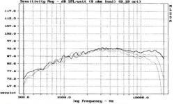
These are generally cones made of paper ( with all sorts of treatments...), or polypropylene, and have a clear rising response above 1khz which kind of extends the bafle step range. As this paper nextel coated 8' from SEAS:
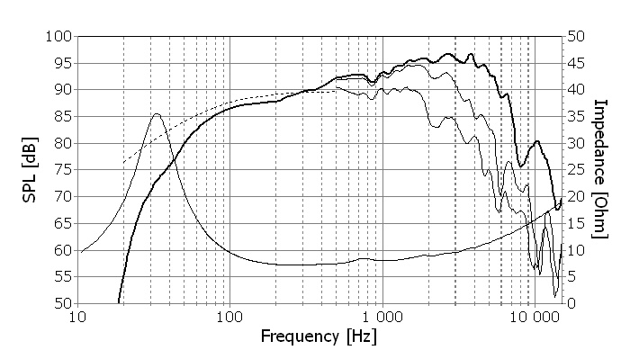
Metal or ceramic cones have a much clearer pistonic behaviour and instead of smoothly rising their breakup zone is weird and unusable. As this aluminium 7' from SSpeak:

In the case of woofers many of them behave as if their effective diameter were decreasing with increasing frequency, making the DI lower than predicted. All full rangers behave like this, and this helps to get a smoother transition to the tweeter, as well as allows to cross higher.
These are generally cones made of paper ( with all sorts of treatments...), or polypropylene, and have a clear rising response above 1khz which kind of extends the bafle step range. As this paper nextel coated 8' from SEAS:
Metal or ceramic cones have a much clearer pistonic behaviour and instead of smoothly rising their breakup zone is weird and unusable. As this aluminium 7' from SSpeak:
- Status
- Not open for further replies.
- Home
- Loudspeakers
- Multi-Way
- A question about directivity in Boxsim simulation