For both: what do you think about the assumed more musical "lively" impact of the low order filters spoked about some reply ago? I believe it's true..
I prefer low order LR2 or evenLR1. But sometimes you have not the choice for question of time alignment between drivers and must use higher orders with some kind of asymetry too, to get proper phase tracking around the xover point.
Unless of course you go active with delay, or use a passive phse corrector as suggested above.
AllenB thinks, that early reflections are as important as output power is, as we can distinguish sound reflected just once by ground and ceiling from the fuzzy reverb tail reaching us later.
Floor and ceiling are part of our daily experience at our home sweet home, listening to music, or making our daily routine. No problemo with floor/ceiling bounce for me, nor feel like moving to a cloud, for the moment...😀
I tried not to let my preferences influence my replies, the physics is the same even if designs are different 😉
It doesn't matter much if you use a notch filter or not, whether you make three changes or one change that affects all three regions, if you get the same end curve the result should be about the same.
There are some specific things to avoid though with filters such as anything too extreme. A Q=1 shouldn't be a problem if it is warranted. Some drivers behave badly outside their useful range. Cone breakup is one example, and the behaviour can be chaotic which means there is no reasonable way to fix it, certainly not with a crossover.
I mentioned this third paragraph in post #26. If the reverberant sound has a different response character than the direct sound then it is more difficult to make the room disappear, and to get the response right.Please can you explain to me better this piece in 28th reply?
If you draw a curve through the three lines I put on the woofer response it will make a smooth curve with a crossover point around 2kHz. I haven't checked anything, it is the direction of the changes I was hinting at.So, if I understood well the way to obtain corrections descripted in the same reply are to cross woofer a bit lower and to insert an anti-breakup notch, right? Not to insert local equalization nets for example..
It doesn't matter much if you use a notch filter or not, whether you make three changes or one change that affects all three regions, if you get the same end curve the result should be about the same.
I used to believe this. Then I began to understand the reasons. I used to blame the order of filter and I believe I was only guessing that the resultant resonance was an issue. I now believe it is the response, overall vs both frequency and in space, that makes the difference.For both: what do you think about the assumed more musical "lively" impact of the low order filters spoked about some reply ago? I believe it's true..
There are some specific things to avoid though with filters such as anything too extreme. A Q=1 shouldn't be a problem if it is warranted. Some drivers behave badly outside their useful range. Cone breakup is one example, and the behaviour can be chaotic which means there is no reasonable way to fix it, certainly not with a crossover.
I aim for this too, hence the crossover suggestions (first two) were based on the directivity index plot.Now if we align the loudspeaker for flat on-axis response, output power has been reduced by beaming but rises again, when the tweeter sets in. This is what GDO dislikes.
Of course the power response will be different whether looking at the individual drivers response, after considering their interactions (lobing), adding diffraction, adding room reflections etc. Some of these are based on shape, eg. rooms aren't round, lobing is sometimes inevitable, diffraction is physically displaced, and not all reflections are created equal.
An optimal crossover can involve deconstructing these, prioritising them and reconstructing. There isn't a program that does this automatically that I know of.
Last edited:
I have another proposal, build a crossover with less phase distortion, see:
...cut...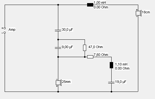
This will sound thin because of a deep and wide off-axis midrange gap (slip tweeter plate under woofer basket as far as possible in order to reduce distance) but also more impulsive because of less phase twist (and, if the amp is weak, because of higher sensitivity).
Excuse me Grasso789, I gave a try but there are some issues I can't explain, in response and in phase while directivity is about the same, you might have used different drivers. However my question is: does the off-axis improvement you said (deep and wide off-axis midrange gap) depend by filter order (1st) or by the change of the cross-point? As I understood from all these replies cross-point is the only factor which can affect the off-axis response..have I misunderstood?

Here's my simulation (dotted my previous version):
View attachment 555760
Are you trying to get a flat power response? This does not sound any good, and also gives a rising response on axis that will oblige you to listen off axis.
What i personnaly do is similar, but with a monotonically falling power response similar to usual room curves used for dsp room correction.

Btw, the values of the components a very unusual. All the xovers used for similar designs use similar circuits with similar values. There's a nice collection of them at Troels Gravesen website to tweak/hack from. Nothing new under the sun...😉
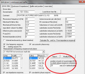
It is also critical to enter a realistic value for the woofer offset in order to get a realistic phase tracking too...
Attachments
Last edited:
An optimal crossover can involve deconstructing these, prioritising them and reconstructing. There isn't a program that does this automatically that I know of.
As said before, i am not a big fan of sims. For passive xover design, it helps you to find "useful" component values, but far imho from what i would call "optimum" values.
Of course, for guys that trust their sims so much that they never measure anything, these might be called "optimum" anyway, or the usual CAD way...

And for active setups, what do we need any sim for? Get a rough idea when starting from scratch something new, maybe, but won't lead any further. Imho, much better the old build and test a prototype way.
Last edited:
For the tweeter, add a series resistance and play around with values of the other components in order to give it a flat passband response and to reach my goals, which are * not too much level at and below fundamental resonance (else, it overloads) but * same phase for woofer and tweeter around and above crossover point. The woofer would profit from a resonance drain at 4500 Hz, of same topology as the one for the fundamental of the tweeter.Here's my simulation (dotted my previous version):
View attachment 555760
Sims, no. I start with a full set of measurements on each driver before combining them.As said before, i am not a big fan of sims.
- Status
- Not open for further replies.
- Home
- Loudspeakers
- Multi-Way
- A question about directivity in Boxsim simulation