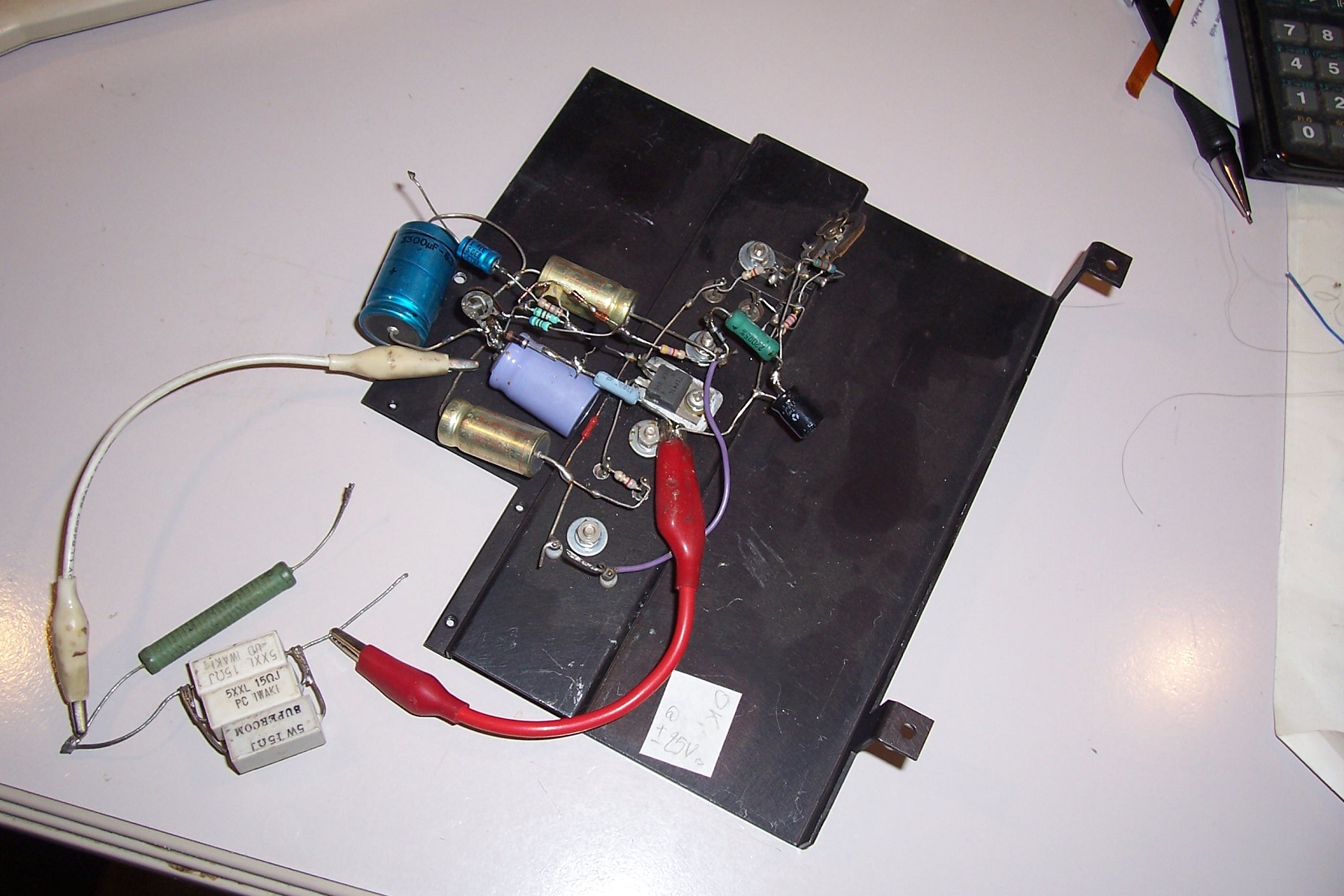
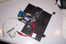
Following this discussion, I dug out one of my early prototype based on N types for the output (and most of the rest).
It is a very crude amplifier, and has not be refined or optimized in any way, but it does have some noteworthy peculiarities:
-Full N output (without the quasi trick)
-No emitter resistors, yet thermally stable
-DC-coupled and compatible with symmetrical supplies despite a natively single supply topology.
I had to reverse-engineer it, as I couldn't find a schematic, but the task was not too difficult, given its simplicity.
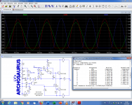
The sim works, but it is not too faithful: it has difficulties driving a 8 ohm load, when the real amplifier easily copes with 4 ohm.
Probably caused by the 2N3055 models, weaker than the real ones.
It wouldn't be difficult to fix though.
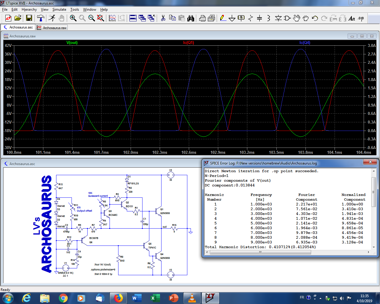
Why did I apparently reject it at the time? Probably because of the performances: something incapable of going below 0.1% THD is not worth pursuing, and the average THD of this amp is around 0.3%, depending on the conditions.
The real amplifier does better than its sim though: it has roughly half the simulated distortion.
There is certainly a lot of room for improvement, and since there is a growing interest for simplistic, old-style amplifiers, such a toy should please many fellow DIYers (and it's a tweaker's heaven!).
It would be very easy to convert it back to a single-supply, capacitor-coupled configuration.
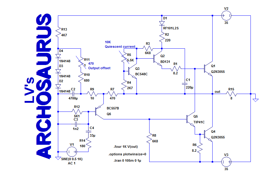
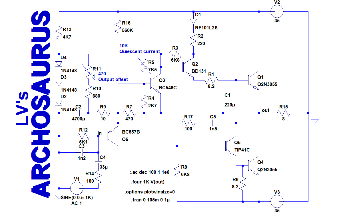
The topology is fundamentally a totem-pole, but with some deviations: normally, R1 and R6 should be connected between E and B of the OP, with a CCS instead of Q2/Q3, and emitter resistors for thermal stability.
With the connection of Q2/Q3, the output transistor is current-driven for quiescent conditions, and Q2/Q3 compensate thermally this current drive (they are coupled to the heatsink).
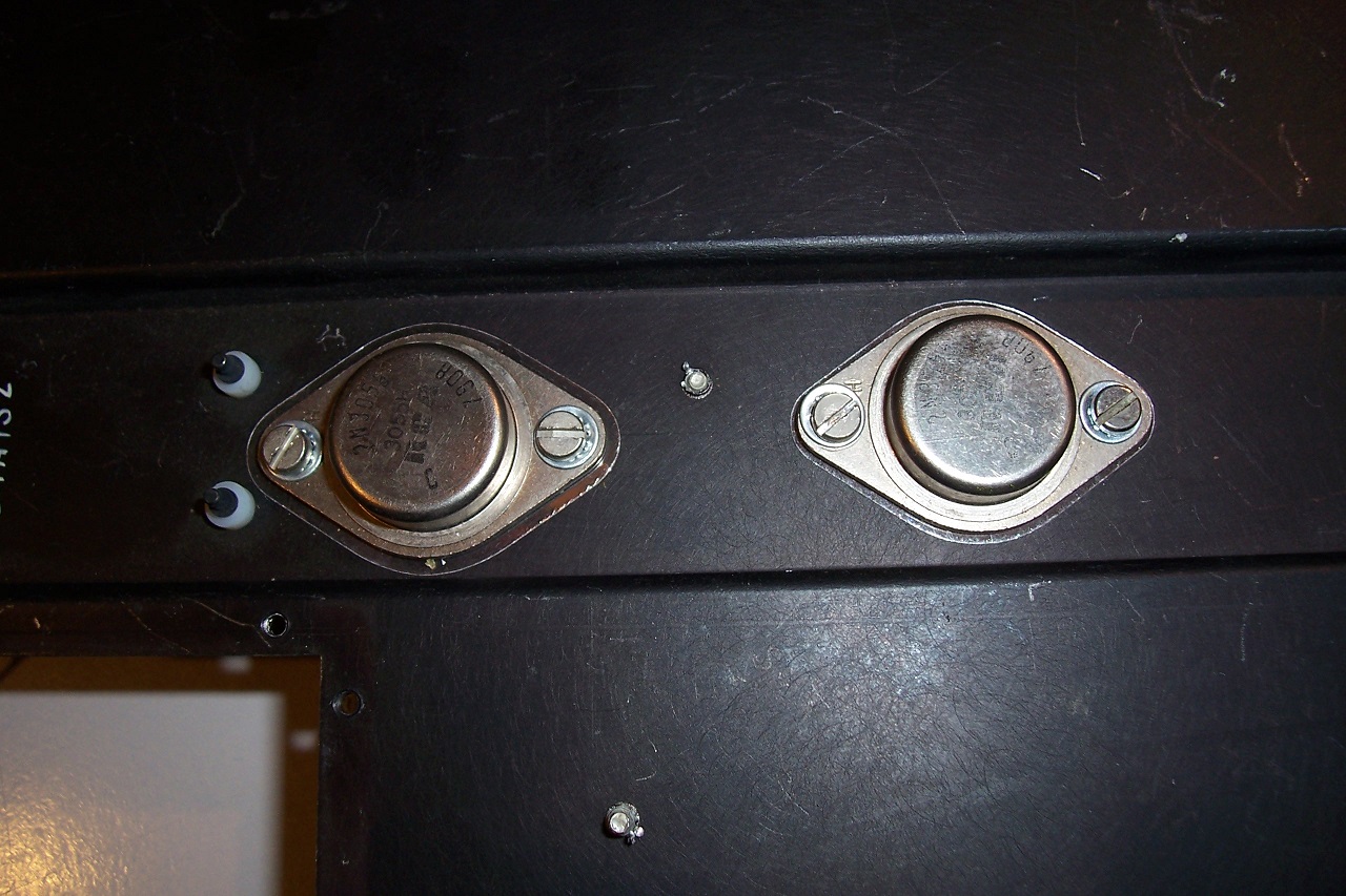
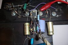
The scheme works well enough: the heatsink is a smallish and flimsy piece of 1mm thick aluminum, the OP's are isolated with ungreased mica's, and the thermal contact of Q3 is not very good, yet it shows no sign of thermal runaway.
This is the 2N3055 model I used, it is the closest to reality I could find, but it is not perfect:
.model Q2N3055 NPN(Is=974.4f Xti=3 Eg=1.11 Vaf=50 Bf=99.49 Ne=1.941 Ise=902.5p Ikf=4.029 Xtb=1.5 Br=2.949 Nc=2 Isc=0 Ikr=0 Rc=.1 Cjc=276p Vjc=.75 Mjc=.3333 Fc=.5 Cje=569.1p Vje=.75 Mje=.3333 Tr=971.7n Tf=39.11n Itf=20 Vtf=10 Xtf=2 Rb=.1 Vceo=60 Icrating=15 mfg=Texas)

Have fun!!!
It is a very crude amplifier, and has not be refined or optimized in any way, but it does have some noteworthy peculiarities:
-Full N output (without the quasi trick)
-No emitter resistors, yet thermally stable
-DC-coupled and compatible with symmetrical supplies despite a natively single supply topology.
I had to reverse-engineer it, as I couldn't find a schematic, but the task was not too difficult, given its simplicity.
The sim works, but it is not too faithful: it has difficulties driving a 8 ohm load, when the real amplifier easily copes with 4 ohm.
Probably caused by the 2N3055 models, weaker than the real ones.
It wouldn't be difficult to fix though.
Why did I apparently reject it at the time? Probably because of the performances: something incapable of going below 0.1% THD is not worth pursuing, and the average THD of this amp is around 0.3%, depending on the conditions.
The real amplifier does better than its sim though: it has roughly half the simulated distortion.
There is certainly a lot of room for improvement, and since there is a growing interest for simplistic, old-style amplifiers, such a toy should please many fellow DIYers (and it's a tweaker's heaven!).
It would be very easy to convert it back to a single-supply, capacitor-coupled configuration.
The topology is fundamentally a totem-pole, but with some deviations: normally, R1 and R6 should be connected between E and B of the OP, with a CCS instead of Q2/Q3, and emitter resistors for thermal stability.
With the connection of Q2/Q3, the output transistor is current-driven for quiescent conditions, and Q2/Q3 compensate thermally this current drive (they are coupled to the heatsink).
The scheme works well enough: the heatsink is a smallish and flimsy piece of 1mm thick aluminum, the OP's are isolated with ungreased mica's, and the thermal contact of Q3 is not very good, yet it shows no sign of thermal runaway.
This is the 2N3055 model I used, it is the closest to reality I could find, but it is not perfect:
.model Q2N3055 NPN(Is=974.4f Xti=3 Eg=1.11 Vaf=50 Bf=99.49 Ne=1.941 Ise=902.5p Ikf=4.029 Xtb=1.5 Br=2.949 Nc=2 Isc=0 Ikr=0 Rc=.1 Cjc=276p Vjc=.75 Mjc=.3333 Fc=.5 Cje=569.1p Vje=.75 Mje=.3333 Tr=971.7n Tf=39.11n Itf=20 Vtf=10 Xtf=2 Rb=.1 Vceo=60 Icrating=15 mfg=Texas)
Have fun!!!
Attachments

So with different (output) transistors (possibly with better models) THD would improve?
What are the requirements for the outputs? It's highly unlikely to find original 2N3055s..
The new ones are even worse than old ones...
What are the requirements for the outputs? It's highly unlikely to find original 2N3055s..
The new ones are even worse than old ones...
With Cordell models, a MOS driver and a few adaptations, it is possible to pass under the symbolic 0.1% level, even in sim.
The requirements for the transistors depend primarily on the output power and load impedance.
Better general characteristics like higher Ft, good Hfe linearity will also result in modest improvements.
Larger improvements would probably require deeper, topological alterations.
The requirements for the transistors depend primarily on the output power and load impedance.
Better general characteristics like higher Ft, good Hfe linearity will also result in modest improvements.
Larger improvements would probably require deeper, topological alterations.
Attachments
Why C4 is 33uF?
That's the biggest input capacitor I've seen...
I see in your prototype build, it actually IS 33uF, so I guess it's not a mistake..
That's the biggest input capacitor I've seen...
I see in your prototype build, it actually IS 33uF, so I guess it's not a mistake..
With simplicity like this and point-to-point wiring, I think this will please a lot of people like me, who like to tinker without needing to implement it via PCBs, protoboard etc. I can see this one finding its way into awkward spaces like small powered speakers, desktop sound etc.
Great ideas, great work and many thanks for posting this latest retro gem, Elvee. 🙂
Great ideas, great work and many thanks for posting this latest retro gem, Elvee. 🙂
What would be the standing current (bias) for this it looks rather class A to me
I cannot do a Sim being a good old boy I do not have the technology about me to do this
Trev
I cannot do a Sim being a good old boy I do not have the technology about me to do this
Trev
No it's not a mistake: I just faithfully reproduced the values used in the working prototype (I prefer to play it safe), but this prototype was for lab evaluation purpose, and I generally prefer to keep impedances at a comfortably low level when possible, because it minimizes the influences such a circuit (open and unshielded) can be exposed to.Why C4 is 33uF?
That's the biggest input capacitor I've seen...
I see in your prototype build, it actually IS 33uF, so I guess it's not a mistake..
This explained the 5K impedance I opted for, and as Anti said:
With such a resistance, 33µF allows a response down to 1Hz.Because R12 is 5K1?
In an actual project (not just for measurement), you would be free to adopt more convenient values: as I said, nothing has been optimized, making this amp a tweaker's dream.
If we look at the input impedance, we see that it is ~700K for the frequency range of interest, meaning R12 could become 47K.
C4 could then be 1 to 2.2µF, for a reasonable bass response.
The input current is about 1µA, and this would add an offset of ~50mV, but since the OS trimmer already exists, it doesn't pose a particular problem
Glad to obligeGreat ideas, great work and many thanks for posting this latest retro gem, Elvee. 🙂
The quiescent current is adjusted thanks to the 10K trimmer R5, and is normally comprised between a few tens of mA (lean class AB) and a few hundreds of mA (hot AB).What would be the standing current (bias) for this it looks rather class A to me
I cannot do a Sim being a good old boy I do not have the technology about me to do this
Trev
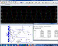
Nothing prevents you from using a 22K trimmer, to bias it firmly into class A; ideally some other values would also need to be adapted.
Here is a crude example:
Note that although the transistor models are not ideal, the THD has now dropped to 0.05%
This has not been actually tested of course, and if you want to use it in class A, you will need to do some homework of your own
Attachments
Svelte!... bla ...
If we look at the input impedance, we see that it is ~700K for the frequency range of interest, meaning R12 could become 47K.
... bling ...
C4 could then be 1 to 2.2µF, for a reasonable bass response.
... bla ...
However, with singleton inputs there may be a slight mismatch in input cap currents balance when the "input" resistor is of higher value; so keeping it low may reduce such un-balance ... making the amp's tone a liiitle "stiffer".
But is that a Good Thing?
For some people, probably including you and me, yes.However, with singleton inputs there may be a slight mismatch in input cap currents balance when the "input" resistor is of higher value; so keeping it low may reduce such un-balance ... making the amp's tone a liiitle "stiffer".
But is that a Good Thing?
Others prefer some even coloration, (which this amp already has, without resorting to artificial tricks, as the dist profile shows) and may welcome such an "addition".
As I warned, this amplifier is rudimentary, and apparently its main purpose was to test the viability of the totem-pole + unusual thermal compensation.
Other aspects were left aside, and that includes supply-voltage stability.
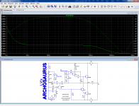
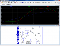
Here is the behavior (simulated, but reliable) when the supply voltages are swept from 15 to 45V:
Below ~25V, there is practically no Iq (the amp carried a warning sticker, so this was acknowledged) and above it rises in an quasi-exponential fashion.
Nothing fatal, and it would still be usable on unregulated supplies, but a more civilized behavior would obviously be preferable.
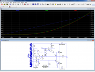
Here is a possible fix: by adding a compensation resistor R16 and readjusting the Iq trimmer, the quiescent current becomes more stable, and is even somewhat overcompensated for higher voltages, which is probably not a bad thing:
Below 20~25V, the amp remains practically dead and inert, but that is caused by the ratio of R2 to R1 and R6: for lower supply voltages, R2 would need to be reduced (or R1 R6 increased, but that could be more problematic).
We can check that this mod hasn't had negative effects on the rest of the amplifier:
In fact, the THD has slightly decreased, so no problem there.
Note that it is just one small aspect: many others can be streamlined/improved: for example, the feedback network uses rather extreme values, leading to a large AC gain and a large blocking capacitor C2.
For testing, it is practical because it reduces the loop gain and acts as a magnification glass for imperfections, but for actual use, more reasonable values would be easier and improve the performances.
These are just a few examples... there is still a lot of room for improvement(s)
Attachments
If you want to torture this topology further; I see only One Way - a brute force approach. Imho you must make the Q5 either a darlington or a npn-with-a-pnp-follower (as can be done with a classic jlh), thus lessening the input Q load so it can think more clearly. And of course apply compensation as it will be needed in such case ...
And yeah the larger input R; there will be more coloration - but the most important aspect of it imho is the fact that this is a variable; signal-dependant coloration (will "breathe" according to the interaction of input signal and the input cap/input resistor time constant). Sort of.
And yeah the larger input R; there will be more coloration - but the most important aspect of it imho is the fact that this is a variable; signal-dependant coloration (will "breathe" according to the interaction of input signal and the input cap/input resistor time constant). Sort of.
I have to say I wonder about Q5 being a TIP41 and the alleged good performance of the sims.
I built my AX6 with Fairchild brand TIP41C/42C as the drivers. Compared to the surviving ST120 board with RCA TO5 drivers from 1970 and djoffe idle current control modification, the AX6 had inferior high frequency response. Top octave Steinway grand tracks would sound like a budget Wurlitzer console piano with the short upper octave strings. Changing the drivers to On semi MJE15028/29 last month freed up the AX6 board to sound like a Steinway grand on top octave tracks. The output transistors are 1986 NTE181 having similar soa specs as MJ15003. This response has to be below 14 khz as my speakers roll off there as does my Army damaged hearing.
I'm also suspect of 2n3055 @ +-35 v rails. The 1970 homotaxial RCA's wouldn't do that, only in the special selected 40xxx versions. I have actually touched a dinosaur carcass, the 1970 build ST120 I bought blown about 1984. The one surviving RCA TO3 transistor is marked 40bigrustspot. Armstrong 621 from the era called them 40636.
Reviewers reported ST120 from 1966 having dull highs. Somebody on here ran a sim of ST120 and found improved high freq response by changing from 2n3055 to TIP3055. So, are your sims using original 200 khz Ft 2n3055? or modern 4 mhz Ft versions? Have you done a 13 khz mixed 15 khz IMD sim? I don't have equipment besides my ears & speakers to test high freq response here.
Last edited:
Why so low values for the feedback network resistors R7 (470 Ω) and R9 (10 Ω) ?
CFA 😉
I provided some explanations here:Why so low values for the feedback network resistors R7 (470 Ω) and R9 (10 Ω) ?
No it's not a mistake: I just faithfully reproduced the values used in the working prototype (I prefer to play it safe), but this prototype was for lab evaluation purpose, and I generally prefer to keep impedances at a comfortably low level when possible, because it minimizes the influences such a circuit (open and unshielded) can be exposed to.
many others can be streamlined/improved: for example, the feedback network uses rather extreme values, leading to a large AC gain and a large blocking capacitor C2.
For testing, it is practical because it reduces the loop gain and acts as a magnification glass for imperfections, but for actual use, more reasonable values would be easier and improve the performances.
This amplifier is not exactly a blank sheet, but the room for customization is huge.If you want to torture this topology further; I see only One Way - a brute force approach. Imho you must make the Q5 either a darlington or a npn-with-a-pnp-follower (as can be done with a classic jlh), thus lessening the input Q load so it can think more clearly. And of course apply compensation as it will be needed in such case ...
And yeah the larger input R; there will be more coloration - but the most important aspect of it imho is the fact that this is a variable; signal-dependant coloration (will "breathe" according to the interaction of input signal and the input cap/input resistor time constant). Sort of.
We will see what DIYers will make of it....
The sim performance is not alleged, and it is certainly not good: by my standards, 0.4% THD for a semiconductor amp is .... let's say marginal.I have to say I wonder about Q5 being a TIP41 and the alleged good performance of the sims.
The actually measured performance is even somewhat better, which is slightly unusual, but quite possible with such a high THD level
HF/step response is something entirely different, and so far I didn't make any measurement, thus I cannot give any answer for now.I built my AX6 with Fairchild brand TIP41C/42C as the drivers. Compared to the surviving ST120 board with RCA TO5 drivers from 1970 and djoffe idle current control modification, the AX6 had inferior high frequency response. Top octave Steinway grand tracks would sound like a budget Wurlitzer console piano with the short upper octave strings. Changing the drivers to On semi MJE15028/29 last month freed up the AX6 board to sound like a Steinway grand on top octave tracks. The output transistors are 1986 NTE181 having similar soa specs as MJ15003. This response has to be below 14 khz as my speakers roll off there as does my Army damaged hearing.
I'm also suspect of 2n3055 @ +-35 v rails. The 1970 homotaxial RCA's wouldn't do that, only in the special selected 40xxx versions. I have actually touched a dinosaur carcass, the 1970 build ST120 I bought blown about 1984. The one surviving RCA TO3 transistor is marked 40bigrustspot. Armstrong 621 from the era called them 40636.
Reviewers reported ST120 from 1966 having dull highs. Somebody on here ran a sim of ST120 and found improved high freq response by changing from 2n3055 to TIP3055. So, are your sims using original 200 khz Ft 2n3055? or modern 4 mhz Ft versions? Have you done a 13 khz mixed 15 khz IMD sim? I don't have equipment besides my ears & speakers to test high freq response here.
It will be my next sim + measurement job (but I don't expect miracles from this topology with 2N3055's + TIP41: we will see....)
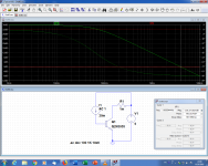
In the meantime, here is the 2N3055 model (from TI) installed in a virtual Ft jig:
As you can see, it is exactly 4MHz, and this is probably no coincidence, if you see what I mean.
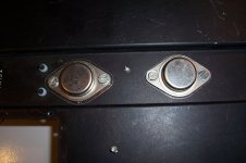
The physical 2N3055 I used are marked "2N3055", then there is the RCA logo and below "3055H" (see pics above). I imagine it means they are hometaxials, but I am not certain.
Anyway, the only measurements I made so far regard linearity.
Speed measurements will follow, hopefully tomorrow if I find some time to do them
Attachments
I have done some measurements, but before proceeding I had to fix the compensation: the results were too good to be true, but a severe peaking/ringing was also present.
This prototype was built to validate the purely DC/thermal aspects, and the rest was left in condition since it didn't hinder the measurements, but here I had no choice.
The compensation is as rudimentary as the amplifier, and it is certainly possible to do better, but it is sufficient to acquire some preliminary results.
Here is the compensated schematic:
With R17/C5, the small signal (1Vrms) BW is 170kHz.
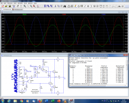
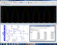
The full power BW is ~32kHz. This value is approximate, because it depends on the way it is evaluated: up to 30kHz, there is no visible degradation of the sinewave, then it becomes progressively more distorted, but the amplitude remains the same up to 45kHz.
At 32kHz, the distortion must be 3~4%.
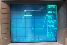
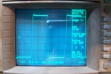
The large signal squarewave response is hideous, with highly asymmetric slew rates:

The moderate amplitude (12Vpp) response is more acceptable, but it is obviously not a race horse:

As I still had spare 2N3055's of the same type, I could measure their Ft: exactly 700kHz (@Vce=5V, Ic=250mA, extrapolation ratio: none=1).
The TIP41C RCA is specified at 3MHz Ft, which is probably more damaging than the slowness of the OP's: it not only plays a driver role, but also works as a VAS and phase-splitter, thus its role is absolutely central, and with 3MHz and 100~120pF Ccb, it is an extremely poor choice.
A much smaller and faster type like BD131 or BD139 would be much better suited to the task.
I also included the 560K Iq compensation resistor and it seems to work as expected.
If required, the thermal compensation can be adjusted by playing on the mounting method of Q2 and Q3: as they work in opposite directions, the compensation can be modulated by the relative coupling between the main heatsink and these transistors: when they are all in contact with the sink, as in my build, there will be an under-compensation, especially if Q3 is just barely touching it (but the amplifier survives that).
If Q3 only has a tight contact with the OP, and Q2 has a separate heatsink, the amplifier will probably be overcompensated.
This prototype was built to validate the purely DC/thermal aspects, and the rest was left in condition since it didn't hinder the measurements, but here I had no choice.
The compensation is as rudimentary as the amplifier, and it is certainly possible to do better, but it is sufficient to acquire some preliminary results.
Here is the compensated schematic:
With R17/C5, the small signal (1Vrms) BW is 170kHz.
The full power BW is ~32kHz. This value is approximate, because it depends on the way it is evaluated: up to 30kHz, there is no visible degradation of the sinewave, then it becomes progressively more distorted, but the amplitude remains the same up to 45kHz.
At 32kHz, the distortion must be 3~4%.
The large signal squarewave response is hideous, with highly asymmetric slew rates:
The moderate amplitude (12Vpp) response is more acceptable, but it is obviously not a race horse:
As I still had spare 2N3055's of the same type, I could measure their Ft: exactly 700kHz (@Vce=5V, Ic=250mA, extrapolation ratio: none=1).
The TIP41C RCA is specified at 3MHz Ft, which is probably more damaging than the slowness of the OP's: it not only plays a driver role, but also works as a VAS and phase-splitter, thus its role is absolutely central, and with 3MHz and 100~120pF Ccb, it is an extremely poor choice.
A much smaller and faster type like BD131 or BD139 would be much better suited to the task.
I also included the 560K Iq compensation resistor and it seems to work as expected.
If required, the thermal compensation can be adjusted by playing on the mounting method of Q2 and Q3: as they work in opposite directions, the compensation can be modulated by the relative coupling between the main heatsink and these transistors: when they are all in contact with the sink, as in my build, there will be an under-compensation, especially if Q3 is just barely touching it (but the amplifier survives that).
If Q3 only has a tight contact with the OP, and Q2 has a separate heatsink, the amplifier will probably be overcompensated.
Attachments

Last edited:
The last square wave image which shows some peaking points to loss of high frequency gain.
I'm sure you know why.
I'm sure you know why.
Last edited:
Perhaps you could do the following: (a) drop the supply to somewhere around +/-20V and replace the 2N3055 with plastic TIP3055 or TIP35's (b) re-align the R2-R1-R6 to the reduced supply. Will this make the squares more symmetric?
To be honest, no: I cannot link a precise hardware detail of the circuit to this particular overshoot.The last square wave image which shows some peaking points to loss of high frequency gain.
I'm sure you know why.
Not in the way you may have in mind anyway, because there is a very down to earth explanation: the discretisation of values.
The optimum compensation network, causing no overshoot for a minimal loss of speed is ~1.65nF/90ohm.
As I use E12 values, I had the choice between 1.8nF/82ohm, giving no overshoot but blunting the edges a little more or 1.5nF/100ohm, less heavy-handed but having a minor overshoot.
I opted for the overshoot.
Using more refined compensation strategies, it would certainly be possible to scrape a little more speed without overshoot or artefacts, but really it would be a waste of time with the transistors of this build.
The Archosaurus validates the principle of the totem-pole output with an original temperature compensation scheme, but to build a working amplifier, one would need to make more sensible choices elsewhere: use "normal" OP transistors, with a Ft > 4MHz (MJLsomething for example), a decent phase-splitter with a > 60MHz Ft, a lower closed loop gain, and a higher input and FB network impedance.
The compensation for such an amplifier would be very different.
Even with the changes outlined above, the slew-rates will remain intrinsically asymmetrical, even if they are faster: much more drive is available for the downwards slope, and to equalize them would require a specific measure, or a suitable input filteringPerhaps you could do the following: (a) drop the supply to somewhere around +/-20V and replace the 2N3055 with plastic TIP3055 or TIP35's (b) re-align the R2-R1-R6 to the reduced supply. Will this make the squares more symmetric?
- Home
- Amplifiers
- Solid State
- A prehistoric amplifier: The Archosaurus