I had a weird thought when catching up on the past posts, particularly from Tom's mention about the variation in the impedance at both the input and the output over the whole range of attenuation (low volume to high volume, I mean!) as per post #182.
We all have assumed that our controlling pot has to be either a log or linear impedance curve, right?
Well, what if we reconfigure this as a completely different curve that will change the impedances of the series and shunt devices independently to produce more linear input and output impedances across the volume range?
A bit along the lines of Uriah's LighterNote but making the curves of the main control pot 'non-standard'.
It is quite possible to alter the curves on commercial pots in various ways (ie Rod Ervine's esp website) or to build some individually calibrated stepped pot curves that aren't log or linear ....
Or, am I just 'blowing smoke' again on this New years day?!
Happy New Year, all! May 2014 hold good health and contentment . . .
James, your thought is actually spot on, and i can do this with the tools I have at hand now and I have thought of it. Since I don't have the math skills or the ability to define R1 and R2 values appropriately -- assuming that it's possible -- I went looking for help from the guy who helps me with complicated spreadsheets that I couldn't do alone, and also raised the question in the Lightspeed thread.
My spreadsheet guy who had already done a ton of work for me at that point said, quite rightly, "first do a proper 10K pot, then we'll talk!" and the Lightspeed thread response was -- silence.
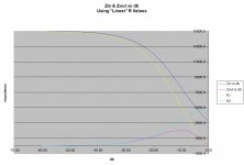
Right now, my friend has provided me with a spreadsheet that shows me the potentiometer's Zin, Zout, and attenuation at various R values which can be specified separately. He's shown me what the curves look like -- including Zin and Zout change with attenuation change -- with both linear and log value responses. I will attach a graph showing a pot with a 15K R1 and 5K R2 which I view as potentially useful for someone with a high gain low impedance setup. I posted this graph on the Lightspeed thread and no one had any comment or suggestion -- maybe it's old hat for the fellows who've been doing this for a while, but seeing the curves for the first time was very educational for me. (Edit: The values in graph are based on 100R source and 10K load, both of which I can change in the spreadsheet.)
So, at this point I don't know what the curves would look like or the details of what kind of resistance values would be required. If, for example, it required precision resistance control of values in the 200K range, I would say it isn't going to be easy because the LDR at 200K would waver probably +/- (guessing) ~10K or more. I have no idea. But I like the idea and computer control of the LDR completely releases one from any preconceived notions of what the R1 and R2 resistance curves should look like. And even if real-world constraints prevent full implementation, certainly you should be able to do a configuration that "leans" in that direction. So your idea is truly an excellent one in my opinion.
Attachments
Last edited:
Jeez, am I brilliant, or what! (the 'or what', methinks!)
Actually, it's really refreshing to write something a bit 'outside the square' and not get condemned by the diyAudio 'snake oil inquisitors'.
Actually, it's really refreshing to write something a bit 'outside the square' and not get condemned by the diyAudio 'snake oil inquisitors'.
Actually, it's really refreshing to write something a bit 'outside the square' and not get condemned by the diyAudio 'snake oil inquisitors'.
Did you know that there is a selection called "ignore list" in your personal control panel? It's like putting someone's email address in your spam list -- you simply don't see posts by that person. I finally had to do that with one individual, and my life on diyaudio got a whole lot more pleasant when I stopped seeing that person's abrasive posts.
AHHH! Great! I see it there, in the Settings section.
I sent a PM just now - did some measuring!
I sent a PM just now - did some measuring!
You guys are on the right track, with wanting to make the input and output impedance stay at more-ideal levels as much as possible.
I did quite a bit of work on that, a few years back, with LT-Spice. I have found a few of my sim files, from that, but not the ones I am looking for. It's been a long time, and I'm old, so I can't remember how good I was able to get the impedance curves. But I think that it's mathematically impossible to make them ideal, or even just as ideal as you might want, with the standard LDR divider setup. However, you can definitely improve on the typical curves, by quite a bit. And you can shape the attenuation (versus knob position) curve fairly well, if you want to. You can also use feedback to perfectly-linearize the LDRs, if you really want to.
I will keep looking for my LT-Spice files from that effort. But I think that I concluded that I would rather just use a couple of nice jfet buffers, or opamp buffers, for each channel. Still haven't built a finished version of any of it, of course.
I think I started out by adding resistors in series and parallel with both the series and shunt LDRs, to see what that could achieve. But I think there was still always a nasty trade-off between good input impedance and good output impedance, although the variations could be minimized, pretty well, especially if you knew exactly what the source and load impedances would be, and especially for only one or the other (i.e. either the input or the output impedance).
Later I started playing with the drive-current curves, in earnest. That's the stuff I can't find. It was pretty slick, if I recall correctly, but couldn't fully overcome the fundamental limitations of the attenuator topology (i.e. the tradeoff between input and output impedance curve manipulation).
But since you're already automating the handling of the LDR drive currents, maybe you could add one or two more LDRs to each channel and solve the problem, fully. I haven't tried to work out whether or not that's theoretically possible. Or, if I did, I have forgotten. It should be easy to do, though.
The math for this stuff isn't hard, theoretically. It's just two-port resistive networks. So it's just basic algebra. Nevertheless, I would tend to recommend using LT-Spice, so you can avoid most of the math and just test your ideas directly, and hopefully define the limits of the "trade space" that's available. You could even just use simple resistors in divider networks (but probably with "parameterized", i.e. variable symbolic resistance values, so you can set their values with "step" directives and sweep and plot whole ranges in one spice run). You probably only need to check the min, max, and middle attenuation values, which could also be done with pencil and paper, or in your head in many cases...
I have some .asc (circuit) files for (the freely-downloadable) LT-Spice that I can post, that have the lightspeed-style control setup, with a working potentiometer component that can be controlled by a voltage source (i.e. with any mathematical construct you care to try), and spice models of the LED-LDR modules that most people are using. I remember also just using two separate current sources, instead of the potentiometer circuit, for when I wanted to try special curves that were more straightforward to generate that way.
You can easily linearize the attenuation response (versus knob position), with the correct drive-current curves. But I don't think doing that helped at all with the impedances. To get those better, I seem to recall the attenuation (versus knob position) looking more like a quasi-inverse-cosine's first cycle, i.e. volume increased slowly at first, then had max slope at the mid-point, then increased more slowly near the top end. But I could be remembering wrongly and that might have nothing to do with the impedance curves. Those (impedances versus knob position) curves were always a bow-shaped curve, at least with the standard lightspeed-type potentiometer setup, bowing up or down significantly in the center, usually with one end higher than the other, if I recall correctly.
I think it was possible to get the impedance curves to stay somewhat flat (and at decent values) in the middle portion of the volume knob's excursion range. But it was a bear to keep them within a good range of values near the highest volume, if I am remembering right. As I am thinking about it, I am remembering more. I think that one basic limitation was not having enough dynamic range in the LDR resistances, in the "good end" of the resistance range that needed to be used. So maybe stacking two LDRs in series for the series element, and paralleling two LDRs for the shunt element, or some other arrangement, could solve that problem (within some limited range of possible i/o impedances, at least). At the time, I was thinking about an all-analog system, with LDRs that would need matching, so there were possibilities that I just dismissed, only because of that inconvenience. Your digital control setup might eliminate some of those considerations or limitations.
I still kind-of wish you had designed-in instrumentation amp circuits that would simply measure all of the relevant voltages and currents and your system could then continuously calculate the actual resistances of the LDRs and use feedback to control their drive currents. That might make this (i/o impedance control) task easier, since the input and output impedances, AND the source and load impedances, could also be continuously measured or calculated (as the case may be). It would probably at least help during the design phase. [Or maybe someone should think about making a one-off "engineering" version with remote sensing, i.e. with an extra pair of wires from input to source and a pair from output to load, so the output voltage signal at the load could be compared to the ideal version calculated based on the input voltage from the source and the attenuation setting. It could also possibly do an FFT to see any degradation versus frequency, which would be nice since the effects of any too-low or too-high attenuator input or output impedance might first become visible only at high or low frequency. You'd see it in the time-domain ideal-minus-actual "error plot", too, but it would be nice to know if and how it varied by frequency. On the other hand, that could all be done in LT-Spice, much more quickly, easily, and cheaply.]
I, too, posted some stuff about better-controlling the input and output impedances, in both the lightspeed thread and the other LDR attenuator thread, with not much interest, especially in the lightspeed thread. But those posts were mostly done before I did the in-depth work on manipulating the drive-current curves, and probably before I had even thought any of this stuff through very well, so maybe there were good reasons that no one was very interested.
I hope that I can find the simulation circuit files from the later parts of that LED-drive-current-manipulation effort, for you, just so you can try to see what's possible (and what's not), more quickly and easily. But if I can't find them (they were created on my old, now-dead computer), I can still post the ready-to-run LT-Spice file for the basic LDR attenuator setup, so maybe someone can at least run some "what if" scenarios without re-inventing the whole wheel.
I'm sorry to have blathered-on for so long, about all of that.
Cheers,
Tom Gootee
Thanks Tom,
As usual, most instructive - I remember some of your development work along these line a couple of years ago and also was a bit surprised at the lack of response, not only by the regular contributors, but also by the lack of interest by the whole community.
I think Paul Haynes was also a bit surprised by the lack of interest and didn't go ahead with anymore kits for his version of the attenuator and doesn't list it on his site now.
There's a whole lot of different people who read these pages but not much lateral thinking - it seems that most of us doing diy aren't that good at doing development work that isn't pretty basic - I fit into that category myself, and lacking computer and SIM ability (and being pretty lazy, too!), rely on you guys for more intelligent progress (this is quite true, IMO)
However, even tho the 'mental muscles' are a bit sluggish these days, I've no problem in following along with much appreciation for your, and others, more critical thinking!
I must put Uriah's Attenuator back into the 'lineup' and systematically go thru the process of changing the impedance settings (ie different series/shunt values for the same attenuation/volume) and see if the character of the sound changes very much using the basic F5 amp ('standard' 100kR input Z) and feed it from my Ayre QB-9 usb dac (must check it's output Z)
I found quite a difference in the sound by altering the ratios of the series/shunt via the separate control modules for the series LDR and the shunt LDR, as you know, but I didn't actually try varying the series/shunt values at the same volume level to see if this changed the sound - I just assumed that the old 'rule of thumb' idea about having 10 times the inputZ and 1/10 value output ratios made it a bit redundant and didn't think anymore about it.
In other words, if the outputZ of the source was about 200R (like a dcB1 buffer) and the load impedance was a steady 100kR (like a basic F5 amp) then, if the input Z of the attenuator was at least 2kR+ (no lower, especially at the midpoint) and the output Z didn't exceed 10kR), then everything would be okay with this combination of source and amp and 'attenuation problem solved' (or, no attenuation problems encountered, yes?)
I don't know if this is actually the case at all volume settings and surprisingly, a recent rough measuring 'check/test' for a repair of a diy Warpspeed kit indicated a quite large dip in the inputZ at the mid volume setting but this didn't appear to effect the sound at all - no doubt, this needs a more detailed and critical test and it's on the 'to do' list.
Isn't it a curious thing that there's so many of us 'older folks' interested in these 'little black devices' .....
Thanks, jh.
Just so others don't get the wrong impression, I should state that this isn't really a huge problem. It might be a problem, sometimes, but probably only in rare cases. But this is diyaudio and overkill is normal, for many here, or at least for me. And I just happen to sometimes enjoy dwelling endlessly on trying to "get the last 0.1 %" (or 0.01%) of the sound quality, since that might be what separates high fidelity from all the rest.
I could be wrong but I am guessing that for most solid-state sources and most cable plus amp or preamp loads, there could never be any detectable problem or variation in sound quality or frequency response, due to a change of any competently-designed LDR attenuator's volume knob position. Tube sources and/or amps have been known to have problems with them, though, due to high output impedance or low input impedance. And there are easy ways to misconfigure or wrongly design audio systems that would make problems much more likely, which is probably more common in DIY systems, although hopefully still rare.
But beyond the obvious cases where a source or amplifier is just a difficult impedance to interface well with, a line-level source and the cable from it always comprise an unknown (in general) RLC circuit, as do an amplifier and its input cable. So changing the R value that one of them sees, i.e. the input or output impedance, WILL change the frequency response, and the attenuation, of the overall signal path. It's just a question of "by how much?" and "how significant would that much be?". If we can't or don't want to try to answer those questions, then the best we can do, for a generic attenuator design, is to provide a high-ish and unvarying input impedance and a low and unvarying output impedance. i.e. We want to present favorable impedance levels, to begin with, and we don't want them to change as we move the volume knob, especially if they are interacting with the frequency response, even if that effect is very, very small.
So, for some systems, it could indeed be a severe problem and solving it would remove a large question mark from the minds of many potential users, and significantly improve their sound quality if using it. For the rest of the systems, it would improve the sound quality (or, rather, decrease the degradation, compared to other LDR-based attenuators) but by a system-dependent unknown (and perhaps often-insignificant) amount. All in all, it would be one less thing to worry about and one more valid claim of superiority. What's not to like, besides any added cost or complexity? Besides, it's a technical challenge (and if not solved, an "imperfection"), for which it would be cool to have found an elegant, robust solution and implementation.
I just wanted to try to clarify the understanding of the scope and severity (or lack thereof) of the problem, and of any potential motivation and effort toward solving it. (I probably won't be able to help much, unfortunately. My energies have been pretty much used-up, lately, by the demands of my day job and by some other issues.)
Tom
Last edited:
It's good to see your old work coming back into consideration and that Steve's developments will possibly 'dovetail' with it.
I'm also not so sure about how the variations of the impedance could/would effect the load and/or source performance or harmonic balance, etc but it seems than we may now have a relatively simple (sorry Steve) method of testing it out with a good deal of accuracy, and not a 'rule of thumb' - I'm a bit surprised that this hasn't been done before this by one of the academics in the AES area.
I meant to mention about a 'sort of extension' to your work in 'modelling the power supply' that Mark Johnson developed in a thread called ....
Simple, no-math transformer snubber using Quasimodo test-jig
A ridiculously simple gadjet that works like a charm - you might find it interesting.
You guys are on the right track, with wanting to make the input and output impedance stay at more-ideal levels as much as possible.
I did quite a bit of work on that, a few years back, with LT-Spice. I have found a few of my sim files, from that, but not the ones I am looking for. It's been a long time, and I'm old, so I can't remember how good I was able to get the impedance curves. But I think that it's mathematically impossible to make them ideal, or even just as ideal as you might want, with the standard LDR divider setup. However, you can definitely improve on the typical curves, by quite a bit. And you can shape the attenuation (versus knob position) curve fairly well, if you want to. You can also use feedback to perfectly-linearize the LDRs, if you really want to.
Cheers,
Tom Gootee
Tom, very nice to hear from you again! Hope you are doing well.
Clearly, you are a SPICE expert and I will probably never even try to learn it – I’ve too much on my plate already. But I am intrigued by your comments:
“it's mathematically impossible to make them ideal, or even just as ideal as you might want, with the standard LDR divider setup”
– so, are you saying that there is a non-standard setup that will work to provide a really good input/output impedance across most of the pot range? Are you proposing something like the “T” arrangement that James has spoken of, or a "Pi" arrangement? The fact is that I do have the kind of control of the LDRs that allows me to create any kind of response curve I want with considerable precision, so creating a three-LDR “T” or “Pi” shaped filter would be quite doable. But there would have to be a pretty good reason to go with that kind of complexity. Of course, the devil is in the details, and if a T or Pi attenuator would require very high value resistances in the range where LDRs are very hard to control, that might be a limiting factor or even a show-stopper.
“However, you can definitely improve on the typical curves, by quite a bit.”
– how would you do that?
“You can also use feedback to perfectly linearize the LDRs, if you really want to.”
– I can already do that without feedback, I just shape the response curve. Right now I am headed toward creating a 10K pot with virtually perfect logarithmic output response from a linear control input.
So, I think I have the tools I need to create the curves you’re talking about, I just don’t know what those curves would look like, and I don’t know how to figure them out. Can you help with that?
Last edited:
Just to keep folks up to speed on what I'm doing --
I think I'm splitting the project into two directions -- one the "cadillac" version and a second, somewhat less capable board that has the advantage of cheaper components and using no SMT technology and therefore easier to build. The CPU heart of the thing does not change -- just the LDR driver configuration.
Discovered the resistor values I'd selected for the prototype were not working well enough and when I do the math I find that I'm pretty far off in two places. Don't know how that happened, I guess I was flying by the seat of my pants when I was prototyping and didn't use the formulas available to me when I originally designed the circuit. I'm going to installed better values today and will see where that takes me.
I hate it when I think I'm wrong and I turn out to be right. Spent much of yesterday afternoon swapping out resistors on my prototype board. While one set of resistors controlling the voltage driving the voltage-to-current chip worked better with a new value that is double what I was using, the change in the current sense resistors for the converter chip turned out to be just right -- after I tried four different values. 😡
Board is now back to working with a slightly better low current limit at about 5 microamps, and the upper limit is unchanged at 11 milliamps. This should be good enough to drive a decent LDR from 50 ohms or less at the bottom to 50K ohms with good control at the top.
The simpler, cheaper board design is back on the drawing board because it now looks like the design will work well if I can find a mosfet with a Vgs(th) of 2V or less and an RDSon of 5 ohms or less at 2 volts. There are lots of power mosfets that meet that criteria, but I'd hate to load the board with a bunch of TO-220s.
The software for both boards would be pretty much the same, so I'll focus on the board I have in hand now and make sure all the software pieces come together before I start working on a second board design.
I have not been idle, I've been working on software and a large part of it is working very well. It looks like calibration accuracy at 50 ohms will be virtually perfect and at 10K ohms +/- 250 ohms worst case, but typically probably better.
This is nowhere near as good as the 20 ohms I achieved earlier, but the conditions are different -- this tolerance is with no control feedback from the LDR resistor, rather only returning to a pre-measured current value and testing the resulting resistance. In other words, this +/- 250 is "real world" operational tolerance to be expected from a working device, not a theoretical tolerance achieved in a testbed. In practice this should be totally inaudible. On my prototype board, I had all four LDRs delivering 10K ohms within that tolerance, so this is no longer theoretical.
The board will have to have two voltages, one above 5 volts to deliver headroom to permit (optionally) two LDRs working in series/parallel for the shunt side to lower shunt resistance to 25 ohms at 10ma, and one substantially below 5 volts to power the logic. The 2N7000 turns out to be not good enough to do the job here (wasted a lot of time fighting that battle) so I'm switching to an IPAK which will require rerouting of a few traces but will do the job extremely well. It takes more space than a TO-92, but less than a TO-220.
I've been happy with the latest board design for quite a while, but I'm not going to do another prototype until the software is practically complete -- the board won't work without the software so no rush there and I'm still discovering enhancements and making small changes. I've changed my current prototype so many times I'm getting nervous about soldering on it any more because the traces and pads are abused already.
I'd like to say more but right now it's almost entirely software.
Last edited:
I've been fiddling with my code, trying to squeeze the very last bit of accuracy I can out of it. A little while ago I was holding 10K resistance at +/- 250 ohms and didn't feel that this was good enough. I now have it down to (I think) below 200 ohms variation and feeling pretty good about it.
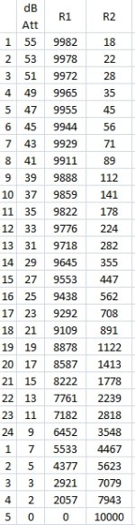
Then I went online and found a website that allowed me to easily get the R1 and R2 resistances for 2dB steps on a 10K pot. I am now wondering why I bothered messing with the precision I've been shooting for -- for R1, two-thirds of the attenuation range sits between 9000 and 10,000 ohms! And on the R2 side, the last 2dB of attenuation spans the range from about 8000 to 10,000 ohms. In other words, a 250 ohm variation at 10K is practically irrelevant!
As the resistance goes down, the accuracy goes up, and at the far end of the range, at 50 ohms, I can control to 1/10th of an ohm. So, in the area where it counts I have very good accuracy, and in the area where it doesn't matter much, I still have pretty good accuracy but not pinpoint accuracy.
Attached are the calculated resistance values I got off the web. This is specified as a 10K pot with output load of 10K ohms.
Attachments
Personally, I think you have achieved a remarkable result and could call this part of your development complete - can this control of the impedances be extended for the equivalent of a 20k, or 50k, pot and still obtain a corresponding reasonable accuracy of impedances?
Thanks for the comments, folks.
@James, I haven't been sitting still on the rest of the code while polishing the control -- the worst part of it -- the piece that is part coding and part intuition/experience -- is pretty much done. What remains is almost entirely just a matter of thinking through the details and straight-forward coding.
@merlin, as the LDRs go up in resistance they become less and less "solid" in terms of control. If they hold +/- 200 ohms at 10K ohms, I'm guessing they'll be much worse at 100K. Pure guess, but I'll bet the resistance will waver +/- 5K~10K. On the other hand, again, in terms of listening it probably won't matter. However, there are other practicalities of calibration that might come into play in that range, and I haven't tested yet.
Edit -- I just did a very quick check with only indirect measuring of the LDR resistance and crude fluctuation indication. It indicated that I can certainly get to 100K and beyond while maintaining control, but sitting at home with my test jig on my desk I don't have the meters to read with accuracy what the resistance actually is and how much it's wavering. So, all I can say is that it looks quite doable.
Last edited:
I have been working hard on the software since last November, and made a milestone today -- for the first time, I ran a full scale calibration.
Using a brute-force method (not the final solution I hope!) I calibrated the R1 and R2 values for a 10K pot equivalent with a minimum resistance of 25 ohms (two 50 ohm LDRs in parallel) for the shunt resistor.
It delivers 52dB of attenuation which I divided into 104 steps of 1/2 db per step. Lots of details left to work out, but I definitely validated something here. The values are very close together and even identical in some places, but the transition between steps should be very smooth indeed. Attenuation levels above 52dB are possible, but would require a larger value pot because the 25 ohm R2 will not change.
This is getting to be a seriously good spec'd device and as such, should find immediate acceptance in the pro field - 52dB attenuation with the less than +/- 0.5dB tracking between the L <-> R channels across the full range is a pretty impressive performance, with the added very low dynamic compression/loss of these devices .......
It's maybe a little early to mention this, but as the programs are coming together, it's an opportune time to suggest a good look at the possibility of adding another series LDR to form a "T" filter instead of the universal "L" pad - the values are somewhat different but I don't think they will present any great difficulty (not a lot more complicated) and I think it maybe possible to reach that 100kR value and an extra level of isolation without any more dynamic signal compression [I'm just guessing a bit here as it's been tooo many years since I've actually done any attenuator design work]
I know a lot of engineers get a bit 'round eyed' and defensive about some of the attenuators like the 'balanced T' and 'Pye form' (split H) etc but they are just a bit more complicated and the advantages/disadvantages have been well understood for some time - it's just now that with the LDRs and your programming that some of these more advanced attenuators maybe possible without the huge cost and device matching nightmare.
You may also just tell me where to go, and ....... ( the same ol' phrase!!)
- Status
- Not open for further replies.
- Home
- Source & Line
- Analog Line Level
- A precision LED/LDR-based Attenuator