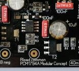
well, in that case the shunt cannot be working. the LEDs are the voltage reference.
as you say, the 10 volt is active.
my best guess is that one of the LEDs (or both) are reversed. It is very hard to see the cathode line on the LEDs, so at the assembly house there is always a small risk this happens.
two options:
DIY (if you can): check very carefully with a magnifying glass the LEDs and compare both channels and see if you can recognize a reversed LED. If so, reverse polarity by de-soldering and re-soldering
Alternatively I suggest to contact Audio Creative for repair / exchange
Hello,
I did have an issue with one of the 4 boards i ordered. I got it replaced for free but had to disconnect everything to remove the board which wasn't working.
Never got feedback why it wasnt working. Probably two small '' transistors '' were switched during soldering and ended up in the wrong spot.
Especially when building a multiple board dac better test all the boards individually before '' piling '' them up.
Doesnt hurt either to compare the boards so things like an inverted led will pop up before actually using the board.
Greetings, Eduard
well, in that case the shunt cannot be working. the LEDs are the voltage reference.
as you say, the 10 volt is active.
my best guess is that one of the LEDs (or both) are reversed. It is very hard to see the cathode line on the LEDs, so at the assembly house there is always a small risk this happens.
two options:
DIY (if you can): check very carefully with a magnifying glass the LEDs and compare both channels and see if you can recognize a reversed LED. If so, reverse polarity by de-soldering and re-soldering
Alternatively I suggest to contact Audio Creative for repair / exchange
First thanks for the quick support!
Also Audio Creative already contacted me, on a Sunday, about the repair
 .
.are the two LEDs are lighting up?
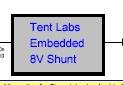
Hey, the power part of the tent lab, embedded 8V triage, there is no detailed circuit diagram, can you send it to study? Thank you
The PCB file was designed with that software and my software could not be opened.
Attachments
Hey, the power part of the tent lab, embedded 8V triage, there is no detailed circuit diagram, can you send it to study? Thank you
The PCB file was designed with that software and my software could not be opened.
Sorry, this is the TENTLABS shunt, which is protected by copyright and is the intellectual property of Guido Tent, hence this is not published
Troubleshooting help - No sound
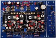
I am building a new DDDAC with one DAC board.
Presently I have a single DAC board and old Mainboard which have been working for about 18 months driven by a RPI on I2s
The new DAC and mainboard came assembled and tested from Creative. I powered it up and measured the require 40mv at the trimmer test points.
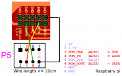
Next step was to put the new board and Dac in the old system as a straight swap to test it. I used the same I2S pinout and leads as before, but I'm getting no sound. I assume that the same I2s pinout will work OK on the new mainboard?
Can anyone help me troubleshoot this please as I'm unsure how to proceed further.
I am building a new DDDAC with one DAC board.
Presently I have a single DAC board and old Mainboard which have been working for about 18 months driven by a RPI on I2s
The new DAC and mainboard came assembled and tested from Creative. I powered it up and measured the require 40mv at the trimmer test points.
Next step was to put the new board and Dac in the old system as a straight swap to test it. I used the same I2S pinout and leads as before, but I'm getting no sound. I assume that the same I2s pinout will work OK on the new mainboard?
Can anyone help me troubleshoot this please as I'm unsure how to proceed further.
Attachments
Last edited:
Dear Alabama,
You also made the connection on the mainboard where You can choose between I2s and S/PDIF input?
You also made the connection on the mainboard where You can choose between I2s and S/PDIF input?
I am building a new DDDAC with one DAC board.
Presently I have a single DAC board and old Mainboard which have been working for about 18 months driven by a RPI on I2s
The new DAC and mainboard came assembled and tested from Creative. I powered it up and measured the require 40mv at the trimmer test points.
Next step was to put the new board and Dac in the old system as a straight swap to test it. I used the same I2S pinout and leads as before, but I'm getting no sound. I assume that the same I2s pinout will work OK on the new mainboard?
Can anyone help me troubleshoot this please as I'm unsure how to proceed further.
Attachments
Doh!
I think I have not connected it. Will look later when I get back home. If I understand it then it's just a link between the centre ground pin and the Is2 pin?
I think I have not connected it. Will look later when I get back home. If I understand it then it's just a link between the centre ground pin and the Is2 pin?
UPDATE - Thanks so much for spotting that Arieason Dank u Val 😉 Music playing and I have to say compared to the original Dac and mainboard this has taken it up considerably in performance already. Can't wait to add the Kali re-clocker with separate PSU's for the RPI and the Kali and see what difference it makes 😉
I have not added the 100K resistors on the outputs yet. Is it best add them between the RCA and chassis ground?
I have not added the 100K resistors on the outputs yet. Is it best add them between the RCA and chassis ground?
Last edited:
Alabama978 - It's good to hear that you got the new DAC sorted out and that it is sounding good. It's a good idea to put the 100k resistors in the circuit. It's standard practice to do so. It is not strictly necessary but the resistors will ensure that the DAC output has a terminated reference to the DAC ground. If there is not a space for them on the main board I would put them right across the RCA connector. There is a signal flow and grounding diagram available in the downloads section of the DDDac1794 web site.
I have a single board kit here, but it will be a while before I get time to build it. I am starting with the wave IO board but I see the potential of the RPI and will probably head down that road if I am happy with the DAC.
I have a single board kit here, but it will be a while before I get time to build it. I am starting with the wave IO board but I see the potential of the RPI and will probably head down that road if I am happy with the DAC.
I suggested the RCA point as a place to mount them but if placed across the RCA i.e. inner and outer pins then I'm thinking it may not be grounded as per the diagram?
The circuit shows chassis ground, so if I am correct the common line on the ouptuts is insulated from the chassis?
Must admit the grounding is the thing I find most confusing.
The circuit shows chassis ground, so if I am correct the common line on the ouptuts is insulated from the chassis?
Must admit the grounding is the thing I find most confusing.
Ignore my last. On revisiting the circuit I see that the resistor goes across the RCA 😱
Will put them in on the final build.
Will put them in on the final build.
But the point about grounding is still valid, isn't it? I find grounding to be very confusing as well. Everything sounds good as it is now, but I don't really know if the grounding is good or not ... I would like to see some good examples of how grounding is done in a complete setup. 🙂
But the point about grounding is still valid, isn't it? I find grounding to be very confusing as well. Everything sounds good as it is now, but I don't really know if the grounding is good or not ... I would like to see some good examples of how grounding is done in a complete setup. 🙂
It's a confusing subject. Here is an article that may be helpful.
Audio Component Grounding and Interconnection
Hi!
can somebody please tell me what the output-impedance with three decks is (before the capacitor)? i only found, that one deck with a capacitor has 130 ohm.
thanks and best regards, mario
can somebody please tell me what the output-impedance with three decks is (before the capacitor)? i only found, that one deck with a capacitor has 130 ohm.
thanks and best regards, mario
The DAC chip output is a current source. The loading resistor will determines the output impedance. For 3 decks your loading resistor would be some where around 45 ohms so that would be the Z out without taking into account the capacitor impedance.
Must admit the grounding is the thing I find most confusing.
I was also confused about this with DDDAC for a long time, and I tried different grounding schemes. Here's a document that Doede made a while ago.
Say I don't have the safety ground in place (think dac on a board), will this affect sound quality, or is it first and foremost safety?
Safety earth is designed for safety purposes. It is often easier to get clean audio signals without safety earth. But safety comes first!Say I don't have the safety ground in place (think dac on a board), will this affect sound quality, or is it first and foremost safety?
- Home
- Source & Line
- Digital Line Level
- A NOS 192/24 DAC with the PCM1794 (and WaveIO USB input)