OK, good. It still looks like a wiring error somewhere. Try to disconnect the PSU parts from each other. Then reconnect step by step to debug the error.The resistance of the POS output to GND is infinite on my controller at the maximum scale.
Thanks Mbrennwa for your answer.
I do not understand that my PSU works properly when it is floating and it melts the fuse as soon as I reference it to ground ?????
Referencing the 0V to ground and earth should not change the current consumption; the grounding is there only to protect the user in case of short circuit thanks to the differential circuit breaker of the domestic installation.
Can the problem can be the bad connection of the secondary R-Core
The colors are as follows:
15V Purple / Gray
15V Blue / Red
Yellow mass
I plugged Gray / Blue for the 0V, Purple on rectifier 1 , Red on rectifier 2 and yellow to earth. Is it correct ?
I also checked the voltages with and without the bleeder:
without bleeder : 22.5V
with bleeder : 13.75
This would correspond to a current of : (22.5-13.75) / 75 ohms --> 117mA ??
I disassembled my psu 12V and checked the entire assembly without finding any error or ground leak.😕😕😕😕
I had the same problem with the fuse that blow up as soon as I turned on the dac. It seems that the wiring diagram of the R-core transformer from Selectronic ( made in India), was wrong. Try to replace the secondary wires.
Effectively there seems to be an error somewhere :I had the same problem with the fuse that blow up as soon as I turned on the dac. It seems that the wiring diagram of the R-core transformer from Selectronic ( made in India), was wrong. Try to replace the secondary wires.
On the trafo
secondary 1 Purple / Gray
secondary 2 Blue / Red
At this time the PM is Gray - Blue
On the site of Sélectronic
secondary 1 Blue / Red
secondary 2 Purple / Gray
and at this time the Pm isRed - Purple
Hello Smooth dancer what Secondary Combination Did You Adopt?
I have verified the phasing of the 2 secondary by putting them in parallel and inserting a 220 V bulb in the primary.
The correct combination in phase of the 2 secondary is Purple - Gray and Blue - Red
Depending on winding number 1 or 2, the combination of the PM will therefore be:
Gray - Blue if the secondary 1 is the Purple - gray ......
Red - Purple if the secondary 1 is Blue - Red
Do you think that's right?😕😕😕
The correct combination in phase of the 2 secondary is Purple - Gray and Blue - Red
Depending on winding number 1 or 2, the combination of the PM will therefore be:
Gray - Blue if the secondary 1 is the Purple - gray ......
Red - Purple if the secondary 1 is Blue - Red
Do you think that's right?😕😕😕
Hi doc 007, I can't remember the right colours in my dac, but it was the diagram on the transformer that was wrong. I just had to try different combinations before I got it right.
I can have a look inside the dac when I'm home tomorrov.
I can have a look inside the dac when I'm home tomorrov.
Hi doc 007, I can't remember the right colours in my dac, but it was the diagram on the transformer that was wrong. I just had to try different combinations before I got it right.
I can have a look inside the dac when I'm home tomorrov.
Thank you to tell me tomorrow the colors of the different secondary of your DAC
I have verified the phasing of the 2 secondary by putting them in parallel and inserting a 220 V bulb in the primary.
The correct combination in phase of the 2 secondary is Purple - Gray and Blue - Red
Depending on winding number 1 or 2, the combination of the PM will therefore be:
Gray - Blue if the secondary 1 is the Purple - gray ......
Red - Purple if the secondary 1 is Blue - Red
Do you think that's right?😕😕😕
I'm not sure I understand this correctly, so I better don't comment on this.
I'd try different options of connecting the secondaries in series and measure the AC voltage across them. If the secondaries' voltages add up to zero, that's the wrong option. If they add up to twice their individual voltages, leave it there. The ends of the series connection then goes to the rectifier diodes, the center connection where the two secondaries meet goes to the NEG output / GND.
Hi Brumiam, fully agreed, the Sowter are a must for this DAC.
The buffer is a valuable upgrade for the single board configuration but the upgrade to 4 boards (with the Sowter) is another huge step ahead mainly in the 3D imagin...
I just do not believe that any transformer is a must. Sorry.
Hello,
I think I have found the reason for my problem.
First I phased the secondary of my transformer R-Core. 2 x 15 V. Grounding is done and I get with the bleeder 13.8V without plugging in the motherboard .
The 5V (Doede) power for the USB also works without problem but as soon as I ground the NEG of this power supply the fuse blows.
Should I just let the 5v power floating?
Does anyone have a logical explanation for this incompatibility?
Thanks
No answer ?Hello,
I think I have found the reason for my problem.
First I phased the secondary of my transformer R-Core. 2 x 15 V. Grounding is done and I get with the bleeder 13.8V without plugging in the motherboard .
The 5V (Doede) power for the USB also works without problem but as soon as I ground the NEG of this power supply the fuse blows.
Should I just let the 5v power floating?
Does anyone have a logical explanation for this incompatibility?
Thanks
I also added a fuse to the general power supply.
2 Amp seems to me sufficient for the 12V supply of the 4 decks and the 5V USB ?
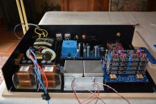
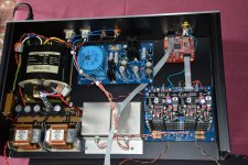
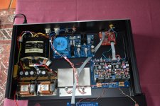
Here are the first photos
Attachments
It seems there is an accidental connection to GND somewhere. Measure the resistances of the PSU outputs to GND.No answer ?
I also added a fuse to the general power supply.
2 Amp seems to me sufficient for the 12V supply of the 4 decks and the 5V USB ?
Here are the first photos
No answer ?
I also added a fuse to the general power supply.
2 Amp seems to me sufficient for the 12V supply of the 4 decks and the 5V USB ?
Here are the first photos
As the pictures do not show a complete wired situation, I like to ask you to make a schematic drawing and post a picture of it.
I am mostly interested in how power supplies connect to where, where you connect Ground and where you connect Chassis. Do not forget the signal out situation please. Do not exclude the 230VAC connected/safety ground. Do you aktually use them in the rest of your system? How is it connected to the next amplifier and the spdif out from your player and what about media player? Only when I see the complete situation, I might be able to help
just to make sure. The DAC works fine? Is it "only" the fact the 5 volt fuse blows when you put the ground to Chassis?
By the way, the 5 Volt should float as it is connected to the USB board Ground, which is the PC Ground, which you do NOT want into your DAC system. Hence the reason the WaveIO is isolated from the I2S bus and the DAC has it is own signal ground. Through the transformers you even Isolate the DAC further, which is good. You should only put the safety ground from the 230VAC to the chassis and connect that with pin 1 of your XLR and NOT connect it at the other end of your xlr interlink (only use pin2 and 3), or if you want pin 1 connected all the way through, do it through a ground breaker setup (I prefer the first)
but let's have a look first on what you did.
Oh, and when the fuse blows, does it blow with cables connected or without cable connected? and if there is a difference, what is it?
Of course there might be a simple wire problem somewhere, but I believe you already said you measured high impedance from NEG 5 Volt to Chassis right?
Last edited:
irrespective of your fuse problem, looking at the picture it looks you wired the XLR wrongly? Like you changed pin 1 and 3. Pls check
By the way, the 5 Volt should float as it is connected to the USB board Ground
Really? The DDDAC docs show the 5 V PSU connected to GND.
Also, all metal parts that are accessible from the outside should be connected to safety earth, and that probably includes the USB plug for the digital input -- or am I wrong?
First thank you for your reply.As the pictures do not show a complete wired situation, I like to ask you to make a schematic drawing and post a picture of it.
I am mostly interested in how power supplies connect to where, where you connect Ground and where you connect Chassis. Do not forget the signal out situation please. Do not exclude the 230VAC connected/safety ground. Do you aktually use them in the rest of your system? How is it connected to the next amplifier and the spdif out from your player and what about media player? Only when I see the complete situation, I might be able to help
just to make sure. The DAC works fine? Is it "only" the fact the 5 volt fuse blows when you put the ground to Chassis?
By the way, the 5 Volt should float as it is connected to the USB board Ground, which is the PC Ground, which you do NOT want into your DAC system. Hence the reason the WaveIO is isolated from the I2S bus and the DAC has it is own signal ground. Through the transformers you even Isolate the DAC further, which is good. You should only put the safety ground from the 230VAC to the chassis and connect that with pin 1 of your XLR and NOT connect it at the other end of your xlr interlink (only use pin2 and 3), or if you want pin 1 connected all the way through, do it through a ground breaker setup (I prefer the first)
but let's have a look first on what you did.
Oh, and when the fuse blows, does it blow with cables connected or without cable connected? and if there is a difference, what is it?
Of course there might be a simple wire problem somewhere, but I believe you already said you measured high impedance from NEG 5 Volt to Chassis right?
I will give you a complete schema of my wiring
To help you better understand my problem I will clarify some things about my first tests.
On the general power supply I added a fuse of 2 A (DAC of 4 decks + USB power supply).
I test my 2 power supplies 12V and 5V without any connection with either the motherboard or the USB module.
The Ground is attached to the mounting screw of the R-Core transformer. At this level I fix the electrostatic screen of the transformer as well as the 0 volt of the 2 power supplies.
My 12V power supply is working properly with the 0V chassis
My 5V power supply also works correctly with the 0V chassis.
But when I put both 0 volts on the chassis, the general fuse (2A) melts but that of the 5V power supply is never melted
Thousand thanks for your help
Pierre
Really? The DDDAC docs show the 5 V PSU connected to GND.
Also, all metal parts that are accessible from the outside should be connected to safety earth, and that probably includes the USB plug for the digital input -- or am I wrong?
Effectively if you look at the photo DDDAC1794 - 2016 schuinvoor of the site of Audio Creative it seems to me that the 5V power supply of the USB module is floating?
So I should not be connecting the 0V of the 5V power supply to the ground 😕😕😕----> end of my power problems🙂🙂🙂
Effectively if you look at the photo DDDAC1794 - 2016 schuinvoor of the site of Audio Creative it seems to me that the 5V power supply of the USB module is floating?
I see how this may avoid ground loops in the USB input, but I believe this is a safety issue. And the DDDAC documentation I linked before does show a GND connection of the 5V PSU.
So I should not be connecting the 0V of the 5V power supply to the ground 😕😕😕----> end of my power problems🙂🙂🙂
It may help to stop killing your fuses. But something is not right. I have both the 0V outputs of the 5V and the 12V PSUs attached to the chassis, which is connected to safety earth. It all works nice and dandy (I had to make sure the USB ground loop does not create too much noise in the data transmission, though).
doc007@
I see we have the same transformer, but mine is connected differently. It looks that you are using a half wave rectifier bridge ? I' m using full wave recrifier bridge where the secondaries Red-Grey and Purple-Blue are connected together.
As Doede already have comment, it looks like you have connected ground (1) on the xlr's.
- Home
- Source & Line
- Digital Line Level
- A NOS 192/24 DAC with the PCM1794 (and WaveIO USB input)