Really? The DDDAC docs show the 5 V PSU connected to GND.
Also, all metal parts that are accessible from the outside should be connected to safety earth, and that probably includes the USB plug for the digital input -- or am I wrong?
I see what you mean, the 5 Volt Ground is shown as a ground sign. You could think all of those are connected together, which is not the case. Maybe I should make a footnote there. Due to the Isolator on the USB Board, you have two "grounds" or commons, the one at the dac side (the WaveIO is supplied with 5 Volt and ´ground from the mainboard) and the ground from the PC and the 5 Volt power supply.
The metal part should be at safety earth through the USB Cable and the PC power connector...
I see what you mean, the 5 Volt Ground is shown as a ground sign. You could think all of those are connected together, which is not the case. Maybe I should make a footnote there. Due to the Isolator on the USB Board, you have two "grounds" or commons, the one at the dac side (the WaveIO is supplied with 5 Volt and ´ground from the mainboard) and the ground from the PC and the 5 Volt power supply.
Ahaaa!! A complete drawing showing the full grounding scheme would be useful (avoiding the use of the same symbol for different "grounds"). Maybe it would be best to entirely avoid the word "ground" (or "GND"), because it can mean so many different things. For example, "safety earth", "analog common", "digital zero", etc. are much more specific, which greatly helps to avoid such confusion.
The metal part should be at safety earth through the USB Cable and the PC power connector...
...if the DDDAC USB is connected to a computer, and if the computer is connected to safety earth (think of a laptop running on battery or a class-II device without a safety-earth connection). Isn't that too many "ifs" for safety?
Here the schematic of my wires in particular the earth and the safery groundAs the pictures do not show a complete wired situation, I like to ask you to make a schematic drawing and post a picture of it.
Attachments
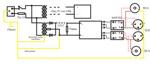
Are you sure the usb board is not connected to anything except it's PSU? ;-)Here the schematic of my wires in particular the earth and the safery ground
Are you sure the usb board is not connected to anything except it's PSU? ;-)
Effectively I did not include the 2 flat cables to the motherboard and the LEDs on the front panel.

Pierre
Effectively I did not include the 2 flat cables to the motherboard and the LEDs on the front panel.
Pierre
I believe the connection between the USB board and the DDDAC mainboard has a "GND" connection (I guess that's "digital zero"), which is probably connected to the NEG output of the 5V PSU. I am writing this out of memory, so you better check if this is correct.
You wrote in an earlier post that you connected the NEG output of the 5V PSU to chassis / safety earth (I believe). This connection is not shown in your drawing. Did you change that in your build?
Also, pin 3 of the XLR outputs are connected to chassis / safety earth via the rings of the RCA connectors, which are connected to the chassis. So pin 3 and pin 1 of the XLRs are connected to each other, which seems wrong to me. I have never tried to combine balanced (XLR) and unbalanced (RCA) outputs in the same unit, so I don't really know what's the best way to do this. Do you really need both?
Regarding your problem with the fuse blowing, I don't really know what's going on. I still suspect some kind of (hidden) wiring error.
Did you measure the resistances of the POS and NEG outputs of your 12V and 5V power supplies to chassis/safety-earth (as suggested earlier)?
Does the fuse also blow if you remove the connections of the PSUs to the DDDAC and the WaveIO board?
The metal part should be at safety earth through the USB Cable and the PC power connector...
...if the DDDAC USB is connected to a computer, and if the computer is connected to safety earth (think of a laptop running on battery or a class-II device without a safety-earth connection). Isn't that too many "ifs" for safety?
I just checked the USB connector of a commercial, CE-approved DAC with USB input (not the DDDAC). The chassis is properly connected to safety earth, but there is indeed no connection to the metal part of the USB connector. I don't know for sure, but it seems it might indeed be okay to have the USB input floating the chassis/safety-earth... mea culpa!
After the intervention of Doede I removed the connection to the chassisYou wrote in an earlier post that you connected the NEG output of the 5V PSU to chassis / safety earth (I believe). This connection is not shown in your drawing. Did you change that in your build?
Hi guys,
From your experience with the DDDAC, is there any difference between analog & digital with common ground and analog & digital with separate ground? Is there any diference in SQ?
From your experience with the DDDAC, is there any difference between analog & digital with common ground and analog & digital with separate ground? Is there any diference in SQ?
Here the schematic of my wires in particular the earth and the safery ground
according to your drawing you have connected the pin 1 and 3 of the xlr connectors together! (through your rca connectors!) ... i am not sure if this is something you want with your nice output transformers ;-)
I only use the RCA outputs and not the XLR. I await the response of Doede.according to your drawing you have connected the pin 1 and 3 of the xlr connectors together! (through your rca connectors!) ... i am not sure if this is something you want with your nice output transformers ;-)
Just wondering if anyone has tested the new Magic 12V PSU on sale at the Audio Creative shop with their DAC?
https://www.audio-creativeshop.nl/winkel/dddac-1794-web-shop/dddac-magic-power-supply/
Interested to hear (no pun intended) what the difference in sound is compared to the stock PSU.
https://www.audio-creativeshop.nl/winkel/dddac-1794-web-shop/dddac-magic-power-supply/
Interested to hear (no pun intended) what the difference in sound is compared to the stock PSU.
I have read, again, the full Doede's article, I think that I will reinstall things how they have to be at the beginning, forget the separation between digital and analgo, between left and right and come back to original design, just supplied by 2 LL1694, and use the LL1638 in my tube amp.
I waste too much time to debug the situation instead of appreciate the music...
Hey billyboyk, did you make it work? If so, I'd be interested to read how you solved the issue.
If anyone wants some spare upgraded Dac boards Version 4.2, I have put some on Ebay.
All working and tested. Type DDDAC in the Ebay search box.
All working and tested. Type DDDAC in the Ebay search box.
Attachments
Last edited:
I only use the RCA outputs and not the XLR. I await the response of Doede.
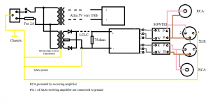
I have been really thinking about your sketch and I tried a few things my self in my hobby room and I was not able to reproduce any problem. The sketch you posted is in fact ok. it should work. That is the technical side of things. What I do my self (for reasons) is to put the safety ground wire (green/yellow) from the power line to the chassis, the transformer screen and pin 1 from the XLR and using cables with the screen connected to pin 1 at ONLY the source side. The hot and cold, pin 2 and 3 are coming from the Output of the sowter transformer. The cinch outputs are floating versus the chassis, so the shielding comes from the signal (or chassis) ground from the receiving amplifier.
Ergo no clue why the fuse blows... but feel free to ignore it and let the 5V unit float with the USB Board
and.... even when you do not use XLR, it would make sense to at least wire them correctly, won't you agree?

Thanks for your answerI have been really thinking about your sketch and I tried a few things my self in my hobby room and I was not able to reproduce any problem. The sketch you posted is in fact ok. it should work. That is the technical side of things. What I do my self (for reasons) is to put the safety ground wire (green/yellow) from the power line to the chassis, the transformer screen and pin 1 from the XLR and using cables with the screen connected to pin 1 at ONLY the source side. The hot and cold, pin 2 and 3 are coming from the Output of the sowter transformer. The cinch outputs are floating versus the chassis, so the shielding comes from the signal (or chassis) ground from the receiving amplifier.
Ergo no clue why the fuse blows... but feel free to ignore it and let the 5V unit float with the USB Board
and.... even when you do not use XLR, it would make sense to at least wire them correctly, won't you agree?
I will rectify my connections and keep you informed
My schema will be the following
Attachments
Small complementary question.
Even if I do not use the XLR plug should I connect on the pin1 the center plug (orange) of the sowter transformer?😕
Even if I do not use the XLR plug should I connect on the pin1 the center plug (orange) of the sowter transformer?😕
I updated PDF documentation of the dddac1794 powered by Tent
I updated the document also on the Download page of my web site
I cannot post it here as the 2MB size exceeds the maximum post length 🙁
you can download here directly:
click - direct link - to version 5.1
I updated the document also on the Download page of my web site
I cannot post it here as the 2MB size exceeds the maximum post length 🙁
you can download here directly:
click - direct link - to version 5.1
- Home
- Source & Line
- Digital Line Level
- A NOS 192/24 DAC with the PCM1794 (and WaveIO USB input)