I suspect I will use 4 more original DAC modules as well as I have them here so that will lower the voltage and less bleed resistor I hope
I managed to get myself in a bit of trouble building 2 PSU's for the DDdac.
I now find myself with the problem that i cannot rectify the ac from the secondaries with the stock PSU's because i only have 1 secondary winding to begin with for each PSU.
The rectifier supplied isn't capable in doing its job because it needs 2 secondary windings.
My question now is: Did Doede design this rectifier on purpose, he probably did!
I did a lot of reading this past week and the full wave bridge rectifier comes out better then the full wave rectifier using 2 diodes but then i read this:
Advantages of Full wave rectifier
• Rectifier efficiency is 81.2%.
• Ripple frequency is two times the input frequency.
• Ripple factor of full wave is 0.48.
Disadvantages of Full wave Rectifier
• It is difficult to locate the centre tap on the secondary winding.
• The DC output is small as each diode utilizes only one half of the transformer's secondary Voltages.
• The diodes used have high peak inverse voltage.
BRIDGE RECTIFIERS
It contains four diodes D1, D2, D3 and D4 connected to form bridge . The AC supply to be rectified is applied to the diagonally opposite ends of the bridge through the transformer. Between other two ends of the bridge, the load resistance RL is connected.
Advantages of Bridge Rectifiers
• The need for center tapped transformer is eliminated.
• The output is twice that of the center-tap circuit for the same secondary voltage.
• The PIV is one half that of the center tap circuit.
Disadvantages of Bridge Rectifiers
• The only Disadvantage of using Bridge rectifiers is that it requires four Diodes .
I also did read both the items on Doede's website about the PSU's on design and how they work, but with my very limited knowledge on electronics i couldn't find any specific clues about this choice of rectification.
So, is doubling the ripple frequency important for the audioquality of the psu?
The other thing is that this type of rectification is used to setup a V+ and a V- but i cannot find the answer to that question also 😕
That leaves me with one question, is it safe for me to asume that i can build a full wave bridge rectifier out of 4 diodes and replace the RBM20200CT to get the same or even better quality in return?
And please elaborate, i want to learn from this

Cheers Paul
I want to modify Doedes standard 12v supply but to power 8 DAC modules. To do this I know I need to upgrade the transformer and to change the final output transistor and heatsink.
What transistor have others used who are powering more than 4 DAC modules please?
Thanks
What transistor have others used who are powering more than 4 DAC modules please?
Thanks
I want to modify Doedes standard 12v supply but to power 8 DAC modules. To do this I know I need to upgrade the transformer and to change the final output transistor and heatsink.
What transistor have others used who are powering more than 4 DAC modules please?
Thanks
Ok found a post from Doede where you just need bigger transformer and heatsink for more than 4 DACs
So now to work out how to do a bigger heatsink? As I have all metal base I might put transistor on that to use as heatsink.
Guys, why don't you go to the Power Supply section of the DIY Audio forum to ask the questions? Also, if you don't know how to design a suitable power supply, the Duncan PSU design software will be helpful (http://www.duncanamps.com/psud2). Its better to think a bit about the PSU design a bit before buying a highly overrated transformer (500VA!!!) with excessive secondary voltage for the DDDAC...
Guys, why don't you go to the Power Supply section of the DIY Audio forum to ask the questions? Also, if you don't know how to design a suitable power supply, the Duncan PSU design software will be helpful (PSUD2). Its better to think a bit about the PSU design a bit before buying a highly overrated transformer (500VA!!!) with excessive secondary voltage for the DDDAC...
Fair play 😉
Hello,
Did start a thread about a power supply with chokes for a device that uses considerable amount of current. It did end after 4 post with 3 post written by myself. Lol
Now don't have anymore questions about the dddac power supply. CLC power supply is not to difficult but with choke input voltage drop across the first choke can be bigger than expected especially if you are building a multiple board dddac with some shunts installed.
Use of a bleeder is necessary to make it work as a choke input. Higher mH chokes need less bleeder current that is why I decided to go for the ll2733.
Whether a 500 VA r core is to big is for me to decide. 2×21 secondary windings in parallel did give me the output voltage I needed using 2 ll2733 chokes. Using 2 ll1694 chokes in a different set up might need another voltage. 2×15volt was to low in my situation and 2×18 would be wrong as well so I got me a 21 volt one.
Greetings, eduard
Hi,
A friend is currently borrowing my DDDac and is experiencing a 'glitch' noise. It only happens on local files from a Synology NAS Drive.
which route through A BlueSound Node 2 Sreamer
NODE 2 : Bluesound
Has anyone else experienced this?
Thanks
A friend is currently borrowing my DDDac and is experiencing a 'glitch' noise. It only happens on local files from a Synology NAS Drive.
which route through A BlueSound Node 2 Sreamer
NODE 2 : Bluesound
Has anyone else experienced this?
Thanks
Hello,
I have too much background noise on music recrorded on low volume and I think the output level from my DDDAC is to high. (The treble sometimes become saturated)
Compared to my previous Dac, I have to diminish the volume almost by half on the amplifier.
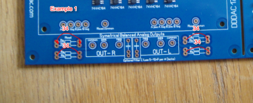
I have a 4 board dddac with the cinemag on output. I placed 4 34 OHM resistors on the 4 spots dedicated as described on the image provided. (Thanks to the advice of eduard)
Should I increase the resistors on the DDAC RA rload places or between the dddac and the cinemags to reduce this problem?
Sincerely Yours,
Laurent.
I have too much background noise on music recrorded on low volume and I think the output level from my DDDAC is to high. (The treble sometimes become saturated)
Compared to my previous Dac, I have to diminish the volume almost by half on the amplifier.
I have a 4 board dddac with the cinemag on output. I placed 4 34 OHM resistors on the 4 spots dedicated as described on the image provided. (Thanks to the advice of eduard)
Should I increase the resistors on the DDAC RA rload places or between the dddac and the cinemags to reduce this problem?
Sincerely Yours,
Laurent.
Attachments
your i/v resistor choices look correct to me. it would be good to check the dc offset on your outputs at the mainboard. If you measure the dc voltage between pos and common and also between neg and common you should see approx 2.7vHello,
I have too much background noise on music recrorded on low volume and I think the output level from my DDDAC is to high. (The treble sometimes become saturated)
Compared to my previous Dac, I have to diminish the volume almost by half on the amplifier.
I have a 4 board dddac with the cinemag on output. I placed 4 34 OHM resistors on the 4 spots dedicated as described on the image provided. (Thanks to the advice of eduard)
Should I increase the resistors on the DDAC RA rload places or between the dddac and the cinemags to reduce this problem?
Sincerely Yours,
Laurent.
Also, is this a totally new DDDAC? because finding the treble a little harsh can be due to it needing to be run in which can take quite some hours! This was not so much a problem with the previous dddac design, but with the new one, there's definitely a 'breaking in' period needed. I guess this is due to the CCS on pin 20.
Thanks for the info Dwjames, I willl make the test.
I got the "old" ddac modules and I let it play for more than a week with burn in songs. The break in should be fine.
I got the "old" ddac modules and I let it play for more than a week with burn in songs. The break in should be fine.
Hi,
I made a test of the output voltage of the DDAC, I get 2.785 volts. As it is not far from the 2.7 volts value I suppose this is not why I get this so strong and sometinmes saturated in the treble.
I would like to try listening without the cinemags. Is it safe to connect my RCA connectors to pos and neg without using a 2.2 capacitor for testing purpose ?
Many Thanks,
A lost guy
If you are using a valve pre or something that won't be bothered by a little DC offset yes. If in doubt use a cap
Hello,
I guess all dddac owners do have the means to take a 2 month holiday? Even during my short stay in Asia i visited this thread during the time i had to wait for my breakfast to arrive. Have been back almost 2 weeks and within one or two hours after firing up my set it started to sound real good.
keep those messages coming. greetings, eduard
Attachments

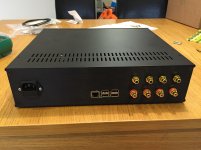
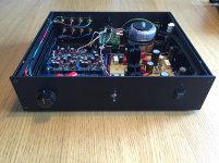
My DDDAC continues to evolve. It's now part of a two-box DAC/streamer project. The power supplies are in a separate box. I've recently changed my old DAC board for the new one and changed from Charcroft to Rhopoint I/V resistors. I was late to the party with Ian Jin's FIFO project, but it has transformed the sound of my system. This is a superb set of boards which really lets you hear what the DDDAC is capable of.
James

James
Just to Jeep the thread alive... Here's few pics of my humble single board DDDAC/Raspberry/Hifiberry/Moode Audio media player. I made the 5 V and 12 V power supplies according Doede's schematics to a perf board. Source is Raspberry pi 2 with Hifiberry DAC+pro which is working as a i2s reclocker and is connected to DDDAC via i2s. Not fancy on the outside, but the sound is great. Oh, and I just recently added a toslink to coax transformer board and new I can use toslink sources as well.
Edit: Hmm, I can add only one pic as an attachment. Maybe it's because of my iPad?
Edit: Hmm, I can add only one pic as an attachment. Maybe it's because of my iPad?
Attachments
Last edited:
Aurender N100H is soon to arrive. I am very exited since it get so many great rewievs.
Doede is very happy about his Aurender too....
Doede is very happy about his Aurender too....
Aurender N100H is soon to arrive. I am very exited since it get so many great rewievs.
Doede is very happy about his Aurender too....
Keep us posted! I have the Aries streamer with Qobuz and love it feeding my DDDAC.
Building my case now and will update with pics once further built
Keep us posted! I have the Aries streamer with Qobuz and love it feeding my DDDAC.
Building my case now and will update with pics once further built
Will do. What did the Aries replace ? Cd player or pc ?
Was it a small og big step forward Simon ?
- Home
- Source & Line
- Digital Line Level
- A NOS 192/24 DAC with the PCM1794 (and WaveIO USB input)