I imagine to proceed as follow: cut all the wires close to the mainboard surface, and simply solder an short extension silver cable (one for each cutted wire) to make the connection with the mainboard. This seems the simpliest for me.
Is there a problem with this simple approach ?
Desoldering is a simple process ones you know what is all about. You just need some cheap tools to do it right.
One is desoldering pump -> https://www.youtube.com/watch?v=wDvgi289dv0
Another is desoldering wick -> https://www.youtube.com/watch?v=htrcZuK_ZsY
Soldering extensions to already existing wires is maybe good for testing, knowing that you will remove them soon. But for permanent solution is much better to replace whole wire. Every soldering adds small impedance to the current and this is what we want to avoid. If we made many solderings to extensions like you say, then the sum of these mini impedances might start giving you signs playing your music. This is very important when it comes to so small currents that we are dealing with in this dac. Soldering tin is not a metal with best conductivity. For our purpose is best to use soldering tin that consist 4% or more of silver. Also silver wires are the best - again - especially when comes to so small currents that we are dealing with, good copper wires are good enough though.
At the end we want to make nice clean work, that will be easy to work with in case of servicing or changes.
Re assuming - less soldering points is BETTER. Less contacts is BETTER.
Saying "cut the wires" I meant to cut them all from underneath the boards as close to the soldering as possible in order to have an easy access with one of mentioned above desoldering tools.
Like this more or less

Leave the wire from top of the boards to hold them with pliers in order to pull them off when unsoldered.
1. Cut them all this way,
2. pull them all out when tin is removed,
3. clean the soldering spots (holes) on board with pump or wick if needed
4. replace all cut wires with new long wire that connect all boards together (preferred silver wires)
I hope this was helpful to you. I'm sure you can find many videos on youtube about that subject.
Good luck
Last edited:
Its about functionality. To me they sound the same. Or If anyone can find any difference it must be very close call.
If it's sounding the same for you, all is fine. We did a comparison with a friend in his system and we both could easily spot quite some differences and both of us prefered Foobar with quite some margin.
But as with all things, it's all about preferences. If you compared them and you like JRiver, it's completely fine. I also understand that you prefer the functionality of JRiver!
I believe it all comes to the rest of the system, speakers, amps, dac, cables. I of course checked both of them, and yes I found some minor differences too, but to say which is better is rather difficult. They are similar, JRiver maybe bit brighter. I saw somewhere some measurements of both, and as there are two opposite camps of lovers and haters, both were rather disappointed when measurements didn't find nothing (if they were valid of course). For sure JRiver is way more versatile, as for HTPC in your living room is difficult to beat. It's kind of all in one HQ software.
Well, foobar is free, and JRiver is not. If this had to be a concern for comparison then of course foobar wins.
I think everyone has to try himself for some time with his system how it goes before making final choice.
Regards
BTW. Did anyone try ArcSoft Total Media Theatre with DDDAC?
Last edited:
Indeed. I bought one of these last weekDesoldering is a simple process ones you know what is all about. You just need some cheap tools to do it right.
http://cpc.farnell.com/duratool/d01849/desolder-iron-sucker/dp/SD01702
I already had a separate solder sucker where you heated with your iron, then swapped it in quickly, but this one with heated tip makes the job sooooo much easier and so cheap too! Wish I had discovered this a few years ago...
Indeed. I bought one of these last week
D01849 - DURATOOL - DESOLDER IRON/SUCKER | CPC UK
I already had a separate solder sucker where you heated with your iron, then swapped it in quickly, but this one with heated tip makes the job sooooo much easier and so cheap too! Wish I had discovered this a few years ago...
Thanks for the indication! Purchased!! Great stuff!
Leave the wire from top of the boards to hold them with pliers in order to pull them off when unsoldered.
1. Cut them all this way,
2. pull them all out when tin is removed,
3. clean the soldering spots (holes) on board with pump or wick if needed
4. replace all cut wires with new long wire that connect all boards together (preferred silver wires)
I hope this was helpful to you. I'm sure you can find many videos on youtube about that subject.
Good luck
I have unsoldered tons of discrete parts using my desoldering station, but in this case, it appeared difficult for me for an unknown reason... I understand the method, and it will be easy to remove the cables from the 4 DAC boards, but (based on my 1st try) I am not sure to get clean and empty holes to insert a new wire...I will try anyway.
A friend of mine is a very good technician, so I will probably subcontract the task if I do not succeed !
Thanks
If you manage to remove the wires, then to clear the holes try to melt residual tin and blow it off with compressed air. Be careful and blow in direction opposite to pcb or secure other components with masking tape or paper. I do it often and it works.
It might be a good idea to put soldering paste on the residual tin before you do it. Put it on also when desoldering. It will make the old solder easy to melt and manage.
Last edited:
I have unsoldered tons of discrete parts using my desoldering station, but in this case, it appeared difficult for me for an unknown reason... I understand the method, and it will be easy to remove the cables from the 4 DAC boards, but (based on my 1st try) I am not sure to get clean and empty holes to insert a new wire...I will try anyway.
A friend of mine is a very good technician, so I will probably subcontract the task if I do not succeed !
Thanks
Yes I understand you now. Last night I had to desolder two capacitors from new boards, and in fact there is a problem to remove the soldering from the pins that are soldered to the common ground holes. This is because there is a quite massive copper used on that part of the boards, and it takes a lot of heat away from the soldering.
The solution to this would be to use desoldering flux and to heat little longer or use more powerful iron.
Please share, if you would find any other good solution to it. Maybe your technician would be happy to share some tips.
Last edited:
Ahh...finally my long time wanted R-core trafo (300va/15v), arrived. Very exited to hear if the SQ will be noticeable improved when compared to the 250va/15v toriodal with epoxy in the senter hole. The toriodal have been serving me well, and it is very silent. No hum at all.
Stay tuned.
Stay tuned.
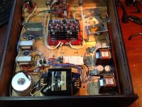
lay out
Hello,
The chokes are in the area where the field from the R core is the strongest. However the circuit is the close to the less radiating area. Turning the chokes with the 4 mounting holes facing the transformer will make them have less influence from the power transformer.
Once you know this R core is a keeper you could try to reduce the cable length going to the rectifier and reduce the cable length from the rectifier to the input choke or the first cap.
I will go for choke input and probably connect the rectifier on the terminal board of the choke.
I think locating the bleeder in another place could also be beneficial especially if it bleeds a big current. I guess it does because you are not using shunts.
Greetings, eduard
Ahh...finally my long time wanted R-core trafo (300va/15v), arrived. Very exited to hear if the SQ will be noticeable improved when compared to the 250va/15v toriodal with epoxy in the senter hole. The toriodal have been serving me well, and it is very silent. No hum at all.
Stay tuned.
Any thoughts here ?
To early. I'm not recovered from having the flu this weekend. Headache and fever is not a good combination. Give me a day or two.
Maybe others with R-core can chime in?
Maybe others with R-core can chime in?
One bad pic from my ipad. Any comments on the layout is welcome.
Like Eduard suggests, it's recommended to keep leads between the rectifier and first Choke short, to reduce ringing.
Since you have 300VA you have sufficient power to try a 2 diode rectifier. I personnaly prefere this over a bridge topology.
Thx stijn
I will fix the leads between rectifiers and first choke.
eduard mention that the bleeder were not in the best position. I thought that it must be a good thing to have it at last after the second choke and caps, so it can draw current through both chokes for good regulation and stability. Or am I missing something.
Since I`m a beginner in this diy game I want to learn as much as I can from you guys.
But I also thrust my ears. "If it doesn`t sound good, it probably isn`t"
bleeder
Hello,
i think especially when the bleeder takes care of a lot of current the wires should be as short as possible. Not sure if you need to put it across the first cap or the cap of the last choke.
in my situation i wanna use the bleeder to just have enough current to be sure it will be a choke input.
because i will use the ll2733 for a choke input i need a transformer with a higher voltage. Tonight i will check if my 21 volt transformer will not give a to high tension for the 25 volt elna caps. Because of the 400mH choke the bleeder current doesnt need to be that high but maybe i will have to drain more current. I did find some info on the minimum current needed in relation to the current used for the circuit. This info is on my other pc i will post it later.
greetings, Eduard
current draw of WaveIO optocoupler?
Hi. Someone knows how much current draws that optocoupler? I'd like to use a better regulator than LF33. Thanks. Pierre
Hi. Someone knows how much current draws that optocoupler? I'd like to use a better regulator than LF33. Thanks. Pierre
Hi. Someone knows how much current draws that optocoupler? I'd like to use a better regulator than LF33. Thanks. Pierre
I have a WaveIO and 1/2 clock delay board. My Belleson SPM78 5.0V regulator barely gets warm with a 7.5VDC unregulated supply. A 12V supply would generate more heat. The I2S processing chips use so little current that an additional 10ma load must be added for a regulator to perform well without the WaveIO isolator load. I don't know the exact current draw, but it can't be much.
update on bleeder current
Hello,
Did find the link about the use of the correct bleeder current.
It is not a lkot of text so not to much a problem to read it all . But if you are in a hurry just take a look at the second drawing at the bottom of the page.
Choke or Capacitor Input?
Greetings, eduard
Hello,
Did find the link about the use of the correct bleeder current.
It is not a lkot of text so not to much a problem to read it all . But if you are in a hurry just take a look at the second drawing at the bottom of the page.
Choke or Capacitor Input?
Greetings, eduard
- Home
- Source & Line
- Digital Line Level
- A NOS 192/24 DAC with the PCM1794 (and WaveIO USB input)