We are honing in.... 166mV is like 35mA which is too low. Are the yellow LEDs lighting up the same the other boas are doing? And do you measure 10 volts at the 7810 output? Is the 3.3 volt also right?.
Strange thing, are Both side showing identical measurement on the DAC board?
Hello Doede have 5 minute break at work
All the led are glowing it is just one channel on one board showing problems.
I will check the 10 and 3,3 volt later after work.
Greetings, eduard
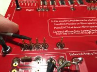
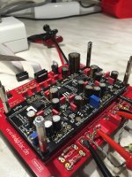
By the way, I used an old red board to test DAC modules....
Just look at the pictures to see how. No need for long wires. These are pins with a small spring inside to have pressure on the contacts. Used in test equipment. What this kind of is 😛
Where would I get the pins, I will have a spare main board soon and would like to make a test board ?
Kind regards, Alex.
By the way, I used an old red board to test DAC modules....
Hi Doede,
Is it an idea to, first, test all boards before shipping to customers?
Bye, Hans
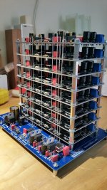
Just re-assembled my 8-deck after many hours of un-soldering. Everything works fine now. And guess what; it produces very fine music even with the lab power supply feeding.
Looks very promising !!
Next; re-calculating my PSU and winding my transformer and choke(s).
Looks very promising !!
Next; re-calculating my PSU and winding my transformer and choke(s).
Attachments
Hello Hans,
They cannot test without the parts you have to solder yourself when you buy the kit.
Better send them the special parts you want to use and ask them to solder and test them and send you the certificate.
Anyway you better test All the little boards before interconnecting them.
Greetings, eduard.
P.'s hope to publish within 8 hours the things Doede did ask me to measure as well
Hello Doede,
I did check all the output voltages at the output terminal of the regulator. They are between 9,75 and 9,91 volt with black pin connected to the negative pole of the power supply cap.
The 3,3 volt is also OK.
The led's all look similar bright to me.
Tonight or tomorrow I will contact audio creative and test their after sales.
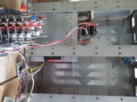
In the attachment you can see the newly made cover with 252 small rectangular holes. Bottom plate will be the same.
Front plate not sure yet.
So anyone has any idea what could be wrong with this half of the board?
Imagine what would have happened if this board did end up in Vietnam?
Greetings, Eduard
I did check all the output voltages at the output terminal of the regulator. They are between 9,75 and 9,91 volt with black pin connected to the negative pole of the power supply cap.
The 3,3 volt is also OK.
The led's all look similar bright to me.
Tonight or tomorrow I will contact audio creative and test their after sales.
In the attachment you can see the newly made cover with 252 small rectangular holes. Bottom plate will be the same.
Front plate not sure yet.
So anyone has any idea what could be wrong with this half of the board?
Imagine what would have happened if this board did end up in Vietnam?
Greetings, Eduard
Attachments
Hi,
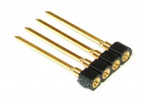
I am not yet in possession of the DDDAC but am seriously considering to have one. The trouble with the wires going all the way through the boards stack is a bit of a problem for me assuming the tinkering buzz which might come when I get a DDDAC. Therefore a question, would it be criminal to use the attached pin/socket to connect the boards all the way through. This way the boards can be stacked/shuffled/disassembled at any time without the trouble.
Regards,
Oleg
Attachments
Hello,
Just did contact with audio creative they will send me a new board tomorrow.
Then i will have to wait a little for some new silmic to arrive but i can start mounting the other parts.
They will take a look at the defective board. Of course they are curious too.
Greetings, Eduard
Just did contact with audio creative they will send me a new board tomorrow.
Then i will have to wait a little for some new silmic to arrive but i can start mounting the other parts.
They will take a look at the defective board. Of course they are curious too.
Greetings, Eduard
would it be criminal to use the attached pin/socket to connect the boards all the way through.
Not at all. Others may disagree, but all the unsoldering involved when removing the boards from the stack is just a major PITA for me... Where can I get these pins?
Hi mbrennwa,
I found them here. Expensive, but I guess if I search more careful better price can be had. I haven't checked Mouser etc. yet. Its just an idea. If Doede approves it would be a great option to buy the necessary amount together with the DDDAC kit from audio creative. It should be much cheaper in bulk quantities also.
Regards,
Oleg
Hi Doede,
Is it an idea to, first, test all boards before shipping to customers?
Bye, Hans
Sorry, impossible as it is a DIY kit. It is not complete, so it cannot be tested....
Where would I get the pins, I will have a spare main board soon and would like to make a test board ?
Kind regards, Alex.
Digikey
http://www.digikey.de/product-detail/de/0914-3-15-20-77-14-11-0/ED1399-ND
Last edited:
It's a nice idea and works well but be careful with your choice as not all are designed to plug together. Those ones look like they are round sockets but square section pins designed for wire wrap and soldering.Hi mbrennwa,
I found them here. Expensive, but I guess if I search more careful better price can be had. I haven't checked Mouser etc. yet. Its just an idea. If Doede approves it would be a great option to buy the necessary amount together with the DDDAC kit from audio creative. It should be much cheaper in bulk quantities also.
Regards,
Oleg
Maybe try to look for 'stackable header pins' I found these were available to be used for arduino projects. Like this
http://cpc.farnell.com/1/1/114553-adafruit-industries-085-arduino-shield-stacking-headers.html
Hi,
I am not yet in possession of the DDDAC but am seriously considering to have one. The trouble with the wires going all the way through the boards stack is a bit of a problem for me assuming the tinkering buzz which might come when I get a DDDAC. Therefore a question, would it be criminal to use the attached pin/socket to connect the boards all the way through. This way the boards can be stacked/shuffled/disassembled at any time without the trouble.
Regards,
Oleg
Oleg, I fully agreed with you and I am using the stackers pins since one year now without any trouble.
I used the Samtec pins SSQ-101-04-F-S that can be purchased directly in the SAMTEC website.
They are square pins so the best way to solder them is to insert all the pins in the stacked boards without soldering, assemble the boards including the motherboard with the standoffs and only when you are done solder the pins.
In this way the pins will be aligned each other..
If not clear I will post some pictures tonight
Regardd,
Enrico
I found them here.
I believe these are not long enough. The PCB distance ob my DAC boards is 18mm, which is the same as the total length of these pins, so there is no more overlap to plug the pins into each other.
Give a look to the SAMTEC website and search for the part number I post before. They are long enough to make a proper contact
Thanks everyone for pointers for the suitable connectors. The parts I showed are just the hints. I guess the best suited part can be selected based on the necessary length and the characteristic contact resistance of the particular model.
My concern about the connectors vs solid wire is the additional series contact resistance between all the boards and the motherboard if connectors are used. If digital signal should propagate to the topmost board, such series resistance of all the connectors that signal has to path may introduce a time delay in the LOW/HIGH signal switching at the DAC chip pins due to the finite rise time of the signal, so the HIGH input level will be reached later for the top most board than it will be for the lowest due to the tiny voltage drop on all the contacts before that board. How much this can be of a problem I do not know but it is easy to calculate knowing the clock frequency of the on-board oscillator (gives the time it takes to "see" the change at the DAC's input pins), signal rise time (tells how long it takes to reach the HIGH voltage level of the DAC chip), HIGH voltage threshold of the DAC chip, and the contact resistance of the selected connectors. I am not talking about the wire/connectors capacitance effect assuming the signal source can provide enough current, and inductance effects since it should be similar for both by the construction. In contrast, wire has always minimal series resistance compared to the connectors which minimizes the effect I described. But may be I am exaggerating the problem which does not exists!? On the other hand it should not be an issue for a single board configuration with connectors🙂
Regards,
Oleg
- Home
- Source & Line
- Digital Line Level
- A NOS 192/24 DAC with the PCM1794 (and WaveIO USB input)