Hello Hans,
I already did mechanically connect my 4 decks together but i will do that one more time after carefully checking the parts that did cause your problem. Happily you are living in the same country as audio -creative so a finding a solution is a piece of cake.
They better do a secure check before sending out any more parcels.
Maybe will add more decks in the future but i am also thinking about getting Aurender like the master himseld is using but i dont know anything about this part of audio.
Greetings, Eduard
What is best ; using the 6K resistor, or the trimmer and the100r ?
When building psu boards from TPA (Placid), I always replaced the trimmer with an fixed resistor. It was simply more stable. The TPA's Placid psu also have shunt regs.
When building psu boards from TPA (Placid), I always replaced the trimmer with an fixed resistor. It was simply more stable. The TPA's Placid psu also have shunt regs.
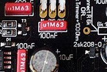
It looks like that particular deck has a different type SMD (FET ?) on board. On all 7 boards the SMD 2SK208 has a grey color and this particular board has on both sides a black SMD fet with a different notation.
It could be that the company who assembled the SMD parts did a mistake on this particular board. Does it look the same like the FET on the TENT shunt area? Close to the LEDs... That is the only other FET on the board. I f that is the case the are two options, send the board to audio creative. They have the batch 2sk208 FETs and can the right component for you. IF you feel you can do it yourself, you can ask to send you a few FETS. Just check the supply voltage to the DAC chip please. This should be 8 volt. Because may be the two FETs were switched....
It could be that the company who assembled the SMD parts did a mistake on this particular board. Does it look the same like the FET on the TENT shunt area? Close to the LEDs... That is the only other FET on the board. I f that is the case the are two options, send the board to audio creative. They have the batch 2sk208 FETs and can the right component for you. IF you feel you can do it yourself, you can ask to send you a few FETS. Just check the supply voltage to the DAC chip please. This should be 8 volt. Because may be the two FETs were switched....
Hi Doede,
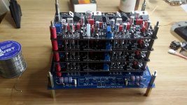
The 8-deck is fully assembled at this moment. It will be a hell of job.
bye, Hans.
What is best ; using the 6K resistor, or the trimmer and the100r ?
When building psu boards from TPA (Placid), I always replaced the trimmer with an fixed resistor. It was simply more stable. The TPA's Placid psu also have shunt regs.
The two are two totaly different concepts, The DAC chip has a voltage source of 2.4 volt and the external resistors of 6k causes a 0,4mA current needed for the BIAS of the analog output. The current source ( FET, Trimmer plus 100ohm) drives the current in the source if you will at a much higher impedance, like few hundred kohm. THis makes a difference in sound quality in the analog stage. So they do sound different. So far everyone likes the current source best.... At the cost of a little bit more complexity. You choose what you like best.... Or try both and decide for yourself? It stays hobby after all 😉
Hi Doede,
The 8-deck is fully assembled at this moment. It will be a hell of job.
bye, Hans.
Doede has a photo of new DAC on his web-site; there's one on Audio Creative site as well.
I compared your photo with the one from Doede's web site, and I can tell with good dose of certainty that the transistors were swapped by the crew who soldered smd devices. Your photo shows a slimmer transistor in place were the wider fet should be present. Just compare your photo with the crop I attached, and it will be clear what happened....
You don't have to disassemble anything; just remove the wrong transistor and solder the correct one in its place.
Nick
Attachments
You don't have to disassemble anything; just remove the wrong transistor and solder the correct one in its place.
Nick
Hi Nick,
You don't have a clear image of the situation;
It's the middle deck of an 8-deck fully assembled dddac.
Both sides, left and right, are wrong. At the left side, the 2SK208 is located at the centre of the deck and there's no way you can reach it.
So, I have to cut all 8 deck's from each other, un-bolt all decks, de-solder al connections (19 X 8 = 152) , place the new/repaired board, bolt it all together. And try to put new silver-wire throug the un-soldered holes and solder again all connections.
Bye, Hans.
Agree. Cut the wires close to the board you want to fix. Lift up and you have access to the swapped transistors.
Hello G600 ,
Probably you are used to present day French engineering.
I think i would just send the complete tower back to audio creative and let them to the job. Probably they are better equipped to do it as well.
Greetings, Eduard
Probably you are used to present day French engineering.
I think i would just send the complete tower back to audio creative and let them to the job. Probably they are better equipped to do it as well.
Greetings, Eduard
Better be safe than sorry
Hello,
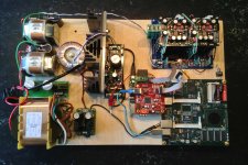
I just did finish connecting the main board with the 4 dac boards. I did use another washer than the washer provided in the kit to give it a little more clearance but did use the original stand offs.
Used the wire included with the kit. The small Teflon tube on the upper board indicates what is left!!!
Must have been expensive wire.
Greetings, eduard
P.'s will connect the power supply later
Hello,
I just did finish connecting the main board with the 4 dac boards. I did use another washer than the washer provided in the kit to give it a little more clearance but did use the original stand offs.
Used the wire included with the kit. The small Teflon tube on the upper board indicates what is left!!!
Must have been expensive wire.
Greetings, eduard
P.'s will connect the power supply later
Attachments
Hi Eduard,
Could you be so Kind and Tell me what Kind of Electrolytics you put on
The boards? The shiny ones.
Regards,
Michael
Could you be so Kind and Tell me what Kind of Electrolytics you put on
The boards? The shiny ones.
Regards,
Michael
Hello Michael,
The small ones are 10 µF and the bigger ones 47 µF both 25 volts Elna silmic 2 types Isolation removed like Supersurfer did.
The small cap near the LF33 regulator is a 22 µF 32 volt Oscon cap.
Greetings, Eduard
The small ones are 10 µF and the bigger ones 47 µF both 25 volts Elna silmic 2 types Isolation removed like Supersurfer did.
The small cap near the LF33 regulator is a 22 µF 32 volt Oscon cap.
Greetings, Eduard
Hello Eduard,
On the main board, we can only see 2 i/v resistors.
The other 2 are under the main board?
On the main board, we can only see 2 i/v resistors.
The other 2 are under the main board?
Hello Grael,
Sure the other pair is on the other side. Because the boards will be mounted vertically putting them on both sides will allow me to mount them closer to the board AND the one in lower position will not heat up the other one.
Be cause they are 2 watt i think it will not be a big problem lol.
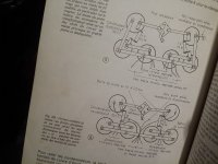
Did you see my copy from the French l'Audiophile magazine about how to connect the power supply caps?
Because the current in this dac is rather high it could make a difference. anyway i will probably listen to Monsieur Hiraga.
In the attachment you can see how Supersurfer did wire his power supply caps. I will use my chokes in differential mode so the GND has to be take at the '' output '' of the last choke.
Doede did tell me that his circuit is low impedance so is not sensitive to chokes which are close by AND the Lundahl chokes have a very small field around them.
I want the output of the caps close to the 12 volt input of the motherboard.
Greetings, Eduard
Sure the other pair is on the other side. Because the boards will be mounted vertically putting them on both sides will allow me to mount them closer to the board AND the one in lower position will not heat up the other one.
Be cause they are 2 watt i think it will not be a big problem lol.
Did you see my copy from the French l'Audiophile magazine about how to connect the power supply caps?
Because the current in this dac is rather high it could make a difference. anyway i will probably listen to Monsieur Hiraga.
In the attachment you can see how Supersurfer did wire his power supply caps. I will use my chokes in differential mode so the GND has to be take at the '' output '' of the last choke.
Doede did tell me that his circuit is low impedance so is not sensitive to chokes which are close by AND the Lundahl chokes have a very small field around them.
I want the output of the caps close to the 12 volt input of the motherboard.
Greetings, Eduard
Attachments
Hello Eduard,
Thanks a lot. Is there any specific reason for removing
The Isolation?
Regards
Michael
Thanks a lot. Is there any specific reason for removing
The Isolation?
Regards
Michael
Hello,
Sure see post 2082 and 2084 of this thread. It is a cheap modification. The first people wring about this were the Japanese and then Jean Hiraga ( who dies have some Japanese blood for sure) start writing about this in France.
Greetings, Eduard
Sure see post 2082 and 2084 of this thread. It is a cheap modification. The first people wring about this were the Japanese and then Jean Hiraga ( who dies have some Japanese blood for sure) start writing about this in France.
Greetings, Eduard
Hi Nick,
You don't have a clear image of the situation;
It's the middle deck of an 8-deck fully assembled dddac.
Both sides, left and right, are wrong. At the left side, the 2SK208 is located at the centre of the deck and there's no way you can reach it.
So, I have to cut all 8 deck's from each other, un-bolt all decks, de-solder al connections (19 X 8 = 152) , place the new/repaired board, bolt it all together. And try to put new silver-wire throug the un-soldered holes and solder again all connections.
Bye, Hans.
I thought only one side needed fixing....
Cutting the wire and then soldering the ends back is not a good idea, as suggested by few others... . Silver plated wire, supplied in a kit, has much higher conductance compared to solder; even 9% silver loaded solder will suffer in this regard. I'd remove all wires (cut them all, and then remove the pieces by heating the eyelets and pulling the wire pieces out with tweezers or similar). You will then need to clean the eyelets with a solder sucker, and then use brand new silver plated wire. It is a painful process with 8 decks!
Nick
- Home
- Source & Line
- Digital Line Level
- A NOS 192/24 DAC with the PCM1794 (and WaveIO USB input)