It's not only to cut the wires. I forgot the standoffs between the deck where you cut the wires. Not so easy to cut theese, it's possible, but,,,,,
I thought only one side needed fixing....
Cutting the wire and then soldering the ends back is not a good idea, as suggested by few others... . Silver plated wire, supplied in a kit, has much higher conductance compared to solder; even 9% silver loaded solder will suffer in this regard. I'd remove all wires (cut them all, and then remove the pieces by heating the eyelets and pulling the wire pieces out with tweezers or similar). You will then need to clean the eyelets with a solder sucker, and then use brand new silver plated wire. It is a painful process with 8 decks!
Nick
I did this MANY times and never was able to hear, measure or see any disadvantage.... We should not be over cautious I think 😉
If the board was in the middle? I just cut the wires of all boards and re-soldered them again. No probs
Hello,
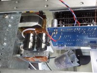
Could not finish it today. Just have to connect the bnc input to the board. Take the board out. Connect it to the 12 volt supply which is pretty close to the board so have to use something to make it a little longer.
The multitude pots are easier accessible when the boards are outside.
Will post again when music is playing.
Greetings, Eduard
quality control
Hello,
I did connect the power to my dddac today and guess what.
All 4 boards i was able to manage to get around 40 mv by adjusting the multiturn pot. all were lower without adjustment.
BUT the left channel board nearest to the main board showed like a value i could not measure. Turning the pot did not help.
Output voltage on the right channel measured pos common neg was 2,9-0-2,9. I forget the exact numbers but pretty close.
The othert channel however was around 1 volt lower.
What could be wrong?
It seems like there is another which will have to be deconstructed.
Greetings, Eduard
When my new decs arrive, I will check every component on the boards to make sure they all are on the right place.
some basic multimeter measurements
Hello,
some results
Channel where everything is ok 2,962-0-2,950 output voltage drop across 4E7 in power supply line next to VB+ around 490mv.
Other channel 1,883-0-1,975 output
The half of the dac board where i cannot get 40 mv ( looks cannot get a reading at all) voltage drop across 4E7 around 166 mv.
This cannot be a cap mounted in reverse i did check them several times before soldering.
the regulators are on the right spot too.
Greetings, Eduard
Output voltage is directly tied to pin20 current draw.
If the regulators are OK, i'll look there, maybe a component problem on that half board...
If the regulators are OK, i'll look there, maybe a component problem on that half board...
Hello,
All the leds on the dac boards lit up. Maybe Doede has some suggestions where to check. Probably will have to cut the wires and send the board to audio creative !!!
At least my power supply is working.
greetings, Eduard
All the leds on the dac boards lit up. Maybe Doede has some suggestions where to check. Probably will have to cut the wires and send the board to audio creative !!!
At least my power supply is working.
greetings, Eduard
Hello,
Let us wait what Doede has to say.
I will probably get my Sowters this week .
I want to get my so called return on investment.
My present Curcio dac is still running strong.
My first post in this dddac thread dates from some time ago long before i did even have some prints. The things i started with was collection the parts of a LCLC power supply and that one is working.
Did work on the chassis too and decided to wait for the boards with the shunts incorporated.
That is all folks, Eduard
Hello,
Hello,
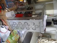
Happily my German engineered cnc machine seldom let's me down so I was able to make the back side of my dddac. No wonder Doede works in Germany.
As you can see no connectors on the back side. They are all on the two sides where they can easily be manipulated.
As soon as there is news about the problem with my circuit it will be put on the Web. Greetings, eduard
Hello,
Happily my German engineered cnc machine seldom let's me down so I was able to make the back side of my dddac. No wonder Doede works in Germany.
As you can see no connectors on the back side. They are all on the two sides where they can easily be manipulated.
As soon as there is news about the problem with my circuit it will be put on the Web. Greetings, eduard
Attachments
Hello,
Happily my German engineered cnc machine seldom let's me down so I was able to make the back side of my dddac. No wonder Doede works in Germany.
As you can see no connectors on the back side. They are all on the two sides where they can easily be manipulated.
As soon as there is news about the problem with my circuit it will be put on the Web. Greetings, eduard
Nice work Eduard !!
Are your problems solved with the 4-deck?
Last edited:
Hello Hans and the others,
No new developments.
Getting personal messages from people who start feeling insecure about starting or continuing their dddac project. It is a shame because there a many people who did invest loads of time and let us not forget money.
The group of people who did continue posting is not to big and there are loads of people just reading and not sharing. The times of Supersurfer and Chanh seem to be gone.
Greetings, Eduard
PS sure after the problem is solved everyone will be informed
Hello,
I did connect the power to my dddac today and guess what.
All 4 boards i was able to manage to get around 40 mv by adjusting the multiturn pot. all were lower without adjustment.
BUT the left channel board nearest to the main board showed like a value i could not measure. Turning the pot did not help.
Output voltage on the right channel measured pos common neg was 2,9-0-2,9. I forget the exact numbers but pretty close.
The othert channel however was around 1 volt lower.
What could be wrong?
It seems like there is another which will have to be deconstructed.
Greetings, Eduard
Sorry to hear things die not work at once. Als I have been writing earlier, many things can go wrong and you need to start checking almost everything like a Sherlock Holmes to deduct on possibilities. The proven way to find errors is to start checking things if they are ok, so you hone in on a possible error.
I have been giving tips a few post ago as well on this. So start with checking the supply voltages 3,3 and 8 volt. Also current consumption by left and right side per DAC board. You can do this by measuring the voltage over the 4.7 ohm resistor. Check all connections again and again and again.... Without power, measure the Rload resistance on top of the decks between common and the A and B points. So you know all boards see the same load.
Is there music? At least at one channel for example? Play a tone of 0 dB 200 Herz and measure with your DMM at ac. You will need 1.2 V rms. The real Voltage will give clues if one board is not playing for example
Things like that. From the above I cannot tell you what is wrong of course. I would be Jomanda... 🙂
Hello,
The part where there is no 40 mv adjustment is also the part where the voltage over the 4E7 is just 166mv
I will check again the voltages 8 and 3,3 when I am home
Back to work, bye bye
The part where there is no 40 mv adjustment is also the part where the voltage over the 4E7 is just 166mv
I will check again the voltages 8 and 3,3 when I am home
Back to work, bye bye
Hello Hans and the others,
No new developments.
Getting personal messages from people who start feeling insecure about starting or continuing their dddac project. It is a shame because there a many people who did invest loads of time and let us not forget money.
The group of people who did continue posting is not to big and there are loads of people just reading and not sharing. The times of Supersurfer and Chanh seem to be gone.
Greetings, Eduard
PS sure after the problem is solved everyone will be informed
I am still here working on my 32 dac board project. 16 dac boards work fine so I am pushing against any boundaries I find to succeed.
I cooked a main board after connecting to the WaveIO board. It seems like the Wave IO board does not keep to IDC rules (pin 1 red stripe) it needs to be reversed ....
This is one of the best Dac`s I have heard, it is well worth the time and effort putting one together.
32 decks!
What is your approach to run the 32 decks? are you using some buffers/drivers for the I2S (like Doede used for his TDA1543 project)? Probably connecting the I2S wire all the way to the 32 decks will case problems (?!).
What do you plan to use for the main PSU?
Best wishes
I am still here working on my 32 dac board project. 16 dac boards work fine so I am pushing against any boundaries I find to succeed.
I cooked a main board after connecting to the WaveIO board. It seems like the Wave IO board does not keep to IDC rules (pin 1 red stripe) it needs to be reversed ....
This is one of the best Dac`s I have heard, it is well worth the time and effort putting one together.
What is your approach to run the 32 decks? are you using some buffers/drivers for the I2S (like Doede used for his TDA1543 project)? Probably connecting the I2S wire all the way to the 32 decks will case problems (?!).
What do you plan to use for the main PSU?
Best wishes
Sorry to hear things die not work at once. Als I have been writing earlier, many things can go wrong and you need to start checking almost everything like a Sherlock Holmes to deduct on possibilities. The proven way to find errors is to start checking things if they are ok, so you hone in on a possible error.
I have been giving tips a few post ago as well on this. So start with checking the supply voltages 3,3 and 8 volt. Also current consumption by left and right side per DAC board. You can do this by measuring the voltage over the 4.7 ohm resistor. Check all connections again and again and again.... Without power, measure the Rload resistance on top of the decks between common and the A and B points. So you know all boards see the same load.
Is there music? At least at one channel for example? Play a tone of 0 dB 200 Herz and measure with your DMM at ac. You will need 1.2 V rms. The real Voltage will give clues if one board is not playing for example
Things like that. From the above I cannot tell you what is wrong of course. I would be Jomanda... 🙂
Hello Doede,
The Rload is the same no matter where i measure.
BUT the dc voltage on the 2 10 µF caps right behind the A and B pos neg soldering spots is just 1,6 volt. At the top board they are all around 8,14 volt.
So NOW you can tell me what is wrong? Does this explain the trimmer not working and the output voltage being lower??
I strongly recommend everybody with a multiple deck dddac to test each dac board seperately by connecting it with some long wires to the motherboard so you will be able to check all the voltages.
i HOPE THIS IS THE START OF THE SOLUTION.
greetings, Eduard
We are honing in.... 166mV is like 35mA which is too low. Are the yellow LEDs lighting up the same the other boas are doing? And do you measure 10 volts at the 7810 output? Is the 3.3 volt also right?.
Strange thing, are Both side showing identical measurement on the DAC board?
- Home
- Source & Line
- Digital Line Level
- A NOS 192/24 DAC with the PCM1794 (and WaveIO USB input)