Nice work Stijn! Anymore infor on the sound other than "understand the fuss"? Can I assume a positive fuss? 🙂
Also, have you try without that 0.1uf wima on Shunt reg? Could your fuss be better understood. 😀
Also, have you try without that 0.1uf wima on Shunt reg? Could your fuss be better understood. 😀
Last edited:
Chanh, I obstained from describing the “fuss”, as so many people had done so already. I also added Silmic’s at the Vcom in 2 out of the four boards, the others are still Oscon’s, so that blurs assessing the shunts.
After a burn-in of about 40hours, I’d say the shunts add more air in the soundstage, everything sounds (much) smoother (this could be the Silmics too) and more detail en, dynamics are inproved. Decays and echo’s just seem to go on forever (in a good way), I’m starting to hear more room acoustics in some recordings and background artifacts, it’s quite amazing..
The dac is like a looking glass which keeps zooming in further, at the time the recordings were made.
How’s the “big” dac getting on? 🙂
btw, who suggested taking of the Wima's, maybe I missed somthing?
Last edited:
instead of Jfet , it's possible to use this http://www.ti.com/general/docs/lit/getliterature.tsp?genericPartNumber=lm134&fileType=pdf
That looks like an excellent candidate, available in a soic-8 packages, per piece at Mouser.
There are quite a few options, this one? LM334SM/NOPB Texas Instruments | Mouser
I wonder if these have small enough a variation, to not have to use an adjustable pot, just a single RSet resistor.
Hi Stijn,
No one suggesting but I did the experiment myself with single DAC board, with and without that Wima 0.1uf and found without Wima on shunt added time and rhythm, noticeably the micro dynamic and decay were apparently obvious! Could this be the mind playing trick?
Oh well, all my 8V Shunts are now without that on board Wima! 🙂
Also readily available a few places in 3 leg, metal can version if you search for lm134hThat looks like an excellent candidate, available in a soic-8 packages, per piece at Mouser.
There are quite a few options, this one? LM334SM/NOPB Texas Instruments | Mouser
I wonder if these have small enough a variation, to not have to use an adjustable pot, just a single RSet resistor.
http://uk.farnell.com/texas-instruments/lm134h-nopb/current-regulator-40v-metalcan/dp/2383109
Glad you like the shunts 🙂 some neat and tidy work as always. I love how with these regulators you get to hear the tiny details which give a real sense of the environment things were recorded in presented to you and without any effort to hear.
Chanh, are you putting your boards together in a way which can be easily disassembled in future? I feel these pin20 tweaks may be simple and very worthwhile, so you may wish to add that soon, or wait a little before assembling everything so you can include those mods too?
I tested a simple adjustable JFET CCS circuit using a 2SK170. Attached is a picture of one I constructed. Doede, like the parts count? Breadboard testing showed that the gate resistor is not needed. A fixed 470 ohm resistor and a 500 ohm pot should work. The 2SK369 and 2SK117 should be suitable alternative JFETS. It is simple and small enough for anyone to build. The 2SK170 and the other JFETs are available on eBay. The main issue is that the 6K resistor is closely surrounded with tall components, so solder access is an issue.
I did a dynamic test with .5v signals imposed on 2.4V to the circuit. The scope showed resultant voltage signal variations of 2.2mv across the 709 ohm source resistor as compared to 0.2mv for the 2 transistor CCS. The signal looked clean. This represents a current variation of about 0.8%. Does Spice simulation provide the types and amounts of distortion expected for these two CCS circuit designs? Supposedly JFETs have even order distortion which is pleasing.
I will wait to see how the 2 transistor CCS sounds after 100 hours of break-in time before I insert the simple JFET boards.
I do like the count! If you take a 1k trimmer (solder first in mid position), your count is 2 😎
your measurements suggest like 100k for single FET and 1M for CCS version...
Of course 1M looks "better", but what if the single FET sounds the same (as you hear no difference anymore?) well THEN there is great alternative, which I am more than willing to implement in the next round of boards as option ...
having said so... if you put a capacitor parallel on the Source resistor, your output impedance will go up dramatically. specially in HF this might be the right thing. 1uF will do a lot already.
For the current control diode, my PCB work is done allready 😛
Hi Stijn,
No one suggesting but I did the experiment myself with single DAC board, with and without that Wima 0.1uf and found without Wima on shunt added time and rhythm, noticeably the micro dynamic and decay were apparently obvious! Could this be the mind playing trick?
Oh well, all my 8V Shunts are now without that on board Wima! 🙂
I didn't realise those Wima's were that big a value, I didn' check. I'll ask Guido about that..
Thanks James! I have been following with great interest! As the result, I still hold off fully assembled my 11-DAC Boards!
May I thanks those contribute to this new development! I look forward for a great outcome. 🙂
Hi Stijn,
Would be great if you could validate via a practical listening exercise? I will post photos later, as am still out and about.
Note - I still have the three Wima 0.1uf on DAC board.
May I thanks those contribute to this new development! I look forward for a great outcome. 🙂
I didn't realise those Wima's were that big a value, I didn' check. I'll ask Guido about that..
Hi Stijn,
Would be great if you could validate via a practical listening exercise? I will post photos later, as am still out and about.
Note - I still have the three Wima 0.1uf on DAC board.
More good work! 🙂I did a dynamic test with .5v signals imposed on 2.4V to the circuit. The scope showed resultant voltage signal variations of 2.2mv across the 709 ohm source resistor as compared to 0.2mv for the 2 transistor CCS..
Out of interest, how do these figures compare with the 6k resistor?
I meant how does the current look with the test signal imposed onto the dc with just the 6k resistor, but I guess it has no option but to respect ohms law and convert the voltage exactly to currentoutput impedance = 6k 😀
Just remember I posted these on other forum.I didn't realise those Wima's were that big a value, I didn' check. I'll ask Guido about that..
More detail photo to come....


Hi Chanh,
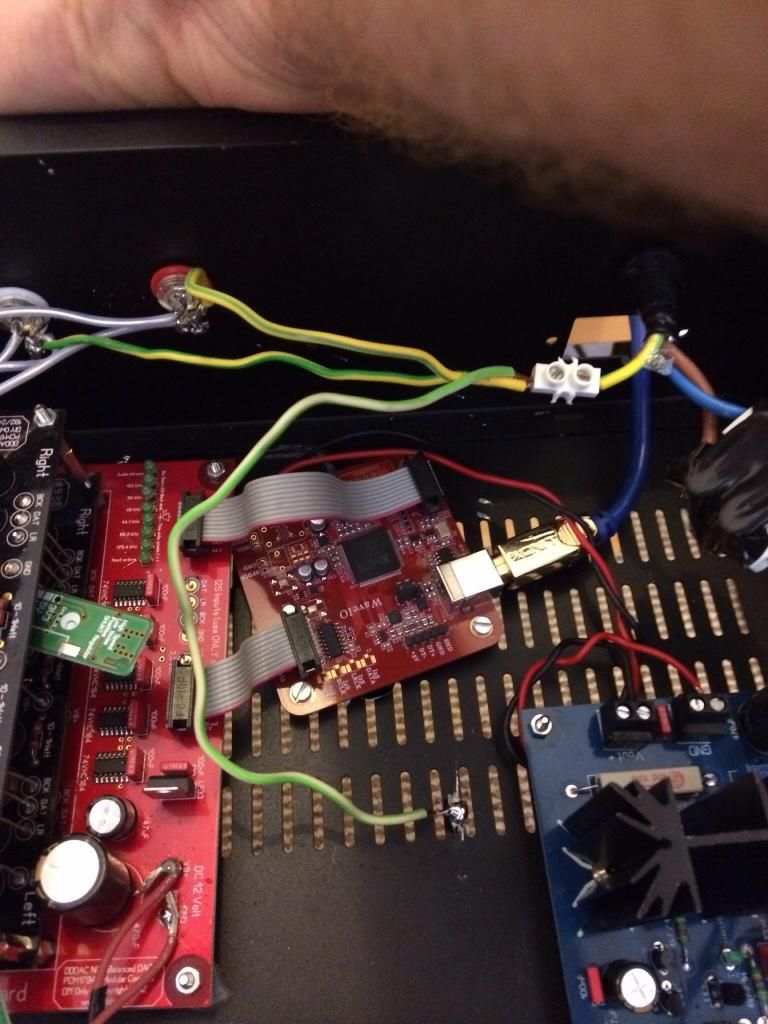
Just "checking" out of interest. Did you have some connections below he PCB as well? I see the 12VDC goes to the old "out" from the 3,3 Volt. Does you connect that somewhere below the board to the Input of the 8volt Tent? Also what will you install at the I2S inputs? I only see one resistor right now?
also If you remove the MKTs from the Tent, that seems to be ok, as now the "reference" for the shunt will be closer to the chip! But in that case for the 3,3Volt you still need the MKT close to the chip, which now isn't?
Or you are just not ready with the board and I am far to early with my comments 😕 😱
I have earthed both the case and the RCA terminals and it still hums like mad, not quite sure what else to do?


and it also humms when you have completely disconnected the yellowgreen earth wire, so that chassis and cinch are floating?
....
I'm not planning on mutilating the shunt boards just yet..
Hmmm, that's kind of the opposite of what I recommended to try... I wouldn't ground the rca to the chassis and wouldn't connect that to mains earth.I have earthed both the case and the RCA terminals and it still hums like mad, not quite sure what else to do?
Unplug a few bits and see if it effects the noise. Have you tried without the USB plugged in? Without the WaveIO connected to the DDDAC? With the WaveIO and USB connected but with no power to the DDDAC?
I have earthed...
That earthing scheme is asking for a hum problem. only connect the RCA negatives to the common output of the dddac main board. Eventuelly if you want to go by the book, you can connect the earth point/star ground, of the dddac powersupply to a "chassis ground" somewhere, which in turn could be connected to mains ground.
Last edited:
Hi all, thanks for your help here. Yes the ddac still badly hums when it is not earthed and all is floating.
James, I have tried all you suggested, ie making sure the one let of the wav10 is not grounded and making sure the RCA terminals are not touching the case etc and it still hummed. As you can see i have tried the exact opposite in earthing all the above, again to a negative effect.
I will try and swap things out bit by bit to see when the hum stopes.
Watch this space ,...
Ok, I disconnected the psu to the DAC board and the hum stopped, not quite sure where to go from here?
- Home
- Source & Line
- Digital Line Level
- A NOS 192/24 DAC with the PCM1794 (and WaveIO USB input)