It's MkIV, version 2. It's the mkIV part which should mean it's the new one with the funky current referenceI see in the picture that this a version 2. there is no CCS on this one, just a resistor connected to pin 20.
I breadboard tested a two transistor CCS circuit and came up with resistor values that provided 0.4ma from a source varying around 2.4v. The current regulating JFET source resistor only drops the voltage about .337v so that leaves just over 2 volts drop for the two transistors. A base voltage to the ZTX450 was provided by a green LED running at 4ma which roughly divides the voltage drop in half across the two transistors. According to data sheets Both the ZTX450 and 2SK170 can operate stably at voltage drops well below 1vdc.
I simulated pin 20 with a variable resistor. The constant current circuit is rock steady over a wide range of voltages. Running the "pin 20" voltage up to 4.0 volts shows no measurable change in current. The "pin 20" voltage was dropped as low as 1.4vdc before the current was reduced by 0.1%.
I am installing these components in a pair of perf boards for testing in my DDDAC board. If the Rakk DAC guys do this with 2 transistors then we can too.
Anyone willing to Spice test a simulation of this circuit?
a couple of thoughts here.
1. By using an LED as voltage reference (not good quality), you give up something in the range of 40dB of rejection (!) compared to a high quality voltage reference.
Good for trying things out, but I suggest putting a true voltage reference in there in the final circuit. Per Salas, LEDs are extremely quiet (I have not personally measured them), but their noise may not be the most important aspect here. It seems that rejection suffers greatly by using them, and especially is we're using B+ with three-legged CCSs (injecting power supply noise), rejection is paramount. .
2. Though the 2SK170 seems to be the favorite child of a lot of the diy world, I think its place is in signal amplification stages, not audio CCSs. Too much capacitance for best performance. Not that it would not do well, but that other JFETs will do better. I suggest sticking with other options, such as the JFETs recommended by the AN103 paper.
this is clearly not normal. can you post a clear picture how you wired it up?
Hi Doede
I had a slightly loose solder joint. I have repaired that and the sound is a lot better, the hum is still there but not quite as bad.
I could post a picture but its a bit of a birds nest in there, as I kind of threw the cinemags in there.
great work guys,
dunno bout you guys but current diodes with 400uA are a little hard to come by here
deviation from 400uA moves vcom voltage, pin 20 v, and output bias v
jfet ccs should be better?
jfet ccss are not basically different than the current regulating diodes... the latter package the former adding sorting then labeling.
but, I'd argue, doing the jfet ccss gives us a lot more room for tweaking. you can try various jfets, Rsets, etc. all good things. just sorting through the possible jfets is a wealth of options in its own, while the current regulating diodes are just a few and even less are available from retailers in a given geography.
Can I just double check that if I wire 2 current regulator diodes in parallel, the total current drawn is just the sum of the 2?
Just for now I've ordered e-301 (300uA) and e-101 (100uA) diodes from mouser with a view to parallel adding them together to give a draw of 400uA on pin20.
I know it's not optimum, but it will be easy and I'm keen to hear how the sound is affected.
Just for now I've ordered e-301 (300uA) and e-101 (100uA) diodes from mouser with a view to parallel adding them together to give a draw of 400uA on pin20.
I know it's not optimum, but it will be easy and I'm keen to hear how the sound is affected.
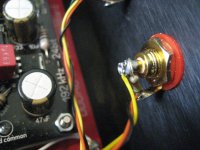
http://i1138.photobucket.com/albums/n533/SovereignKing/imagejpg2-1.jpg
http://i1138.photobucket.com/albums/n533/SovereignKing/imagejpg1-2.jpg
As I said its a birds nest.
Rather than wire the cinemags to the rca's I joined the cinemag wires to the end of the wires going to the rca's, I know it's a bit Micky mouse but I was just wanting a quick demo as I am taking my DAC to a load of Art of Sound members tomorrow for them to hear.
I have traced all the wires back correctly but there is a definite hum that I need to get rid of .


Can I just double check that if I wire 2 current regulator diodes in parallel, the total current drawn is just the sum of the 2?
Just for now I've ordered e-301 (300uA) and e-101 (100uA) diodes from mouser with a view to parallel adding them together to give a draw of 400uA on pin20.
I know it's not optimum, but it will be easy and I'm keen to hear how the sound is affected.
they'll work but with somewhat decreased performance
though , good enough for basic test
they'll work but with somewhat decreased performance
though , good enough for basic test
Good stuff, thanks 🙂
ok... 😱It's MkIV, version 2. It's the mkIV part which should mean it's the new one with the funky current reference
mm, still hard to see what they have been doing 🙄
Can't see from those pics, but are your RCAs grounded to the chassis? best if they're not.I have traced all the wires back correctly but there is a definite hum that I need to get rid of .
Also, are you using a WaveIO? If so, there's one of the mounting holes which you don't want to connect to the metal chassis as it's a grounding point. It's the one with the ground symbol by it.
Does the hum change if your Cinemags aren't sat on the metal chassis?
Worth a quick look at these bits, humming often means you have a grounding issue.
Good stuff, thanks 🙂
in fact you parallel also the two output resistances, hence the somewhat decreased performance, but agree, it will show if there is a positive impact which would motivate further experiments ! 🙂 look forward to your tests....
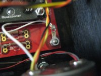
the shadows of the wires are hard to distinguish from the real wires 😱http://i1138.photobucket.com/albums/n533/SovereignKing/imagejpg2-1.jpg
http://i1138.photobucket.com/albums/n533/SovereignKing/imagejpg1-2.jpg
As I said its a birds nest.
Rather than wire the cinemags to the rca's I joined the cinemag wires to the end of the wires going to the rca's, I know it's a bit Micky mouse but I was just wanting a quick demo as I am taking my DAC to a load of Art of Sound members tomorrow for them to hear.
I have traced all the wires back correctly but there is a definite hum that I need to get rid of .
it looks as if you have connected the common to something? just to make sure, leave WaveIO floating, cinch floating and only connect POs and NEG terminal to the primary of the transformer. humm is ground loops in most cases
Ahh yes, hard to see, but looks as though you have the outputs connected to common and pos rather than pos and neg.the shadows of the wires are hard to distinguish from the real wires 😱
it looks as if you have connected the common to something? just to make sure, leave WaveIO floating, cinch floating and only connect POs and NEG terminal to the primary of the transformer. humm is ground loops in most cases
Also looks like you have them wired out of phase, so one is red for pos, the other is brown for pos. That will make you speakers cancel each other out. Make sure they're on pos and neg and that both channels are wired the same.
Thanks Doede and James,
I've delayed my DAC bake off till Saturday now, as I would really like to have the cinemags in the dddac when we have the bake off.
I'll try all the advice given tonight.
Even over the hum there Is a definite improvement in sound .
I've delayed my DAC bake off till Saturday now, as I would really like to have the cinemags in the dddac when we have the bake off.
I'll try all the advice given tonight.
Even over the hum there Is a definite improvement in sound .
Ahh yes, hard to see, but looks as though you have the outputs connected to common and pos rather than pos and neg.
Also looks like you have them wired out of phase, so one is red for pos, the other is brown for pos. That will make you speakers cancel each other out. Make sure they're on pos and neg and that both channels are wired the same.
I know the pictures are confusing but the cinemags are definitely only wired to pos and neg on the left and right channels , and both reds are on the pos and both browns are on negs. So I'm really confused where the hum is coming from, I'll take some clearer pictures tonight.
Thanks
Have you tried this...see pics.
So white wire ( shield) to case ground and black wire to signal ground.
It removed the last tiny bit of hum I had....
So white wire ( shield) to case ground and black wire to signal ground.
It removed the last tiny bit of hum I had....
Attachments
Last edited:
I went past Guido from Tentlabs today to pick up some shunts.. (I only live 30min down the road), and took the opportunity to ask if he had a suggestion on the CCS 0.4mA at 2.4V. He drew up this diagram below saying the BSP135 would be able to do it. The squares are two resistors of several hundred Ohm each, both could be the same value, he seemed to suggest their value wasn't that critical. I’ve been wrecking my brain on the BSP135 spec sheet, but I can’t see how this could work. Maybe you guys can make some sense of it. Also I can’t find a place that will sell small quantities so it might be an none starter anyway.
An externally hosted image should be here but it was not working when we last tested it.
Last edited:
Nice to see some good developments here lately 🙂
Did anyone manage to properly test the effects of different types of caps for the vcom yet? I see a some have gone for OSCON there, but not all...
James, I'm very happy with the Oscon's at the Vcom's. Stefan (Supersurfer) has used Silmic's. I'm actually playing with the idea of doing a mix, 1 or 2 board with Silmic's and the others board with Oscon. See how that sounds. I think the choice of caps here is more a question of personal preference (and the rest of the system) then being (significantly) better or worse.
- Home
- Source & Line
- Digital Line Level
- A NOS 192/24 DAC with the PCM1794 (and WaveIO USB input)