as I wrote before - neg rail is way to go ; say , everything from -5V ...
even if "dirty" one (unregged) will do the job , due to CCS isolation
even if "dirty" one (unregged) will do the job , due to CCS isolation
Another 0.4ma CCS Circuit
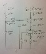
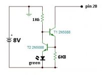
I breadboard tested a two transistor CCS circuit and came up with resistor values that provided 0.4ma from a source varying around 2.4v. The current regulating JFET source resistor only drops the voltage about .337v so that leaves just over 2 volts drop for the two transistors. A base voltage to the ZTX450 was provided by a green LED running at 4ma which roughly divides the voltage drop in half across the two transistors. According to data sheets Both the ZTX450 and 2SK170 can operate stably at voltage drops well below 1vdc.
I simulated pin 20 with a variable resistor. The constant current circuit is rock steady over a wide range of voltages. Running the "pin 20" voltage up to 4.0 volts shows no measurable change in current. The "pin 20" voltage was dropped as low as 1.4vdc before the current was reduced by 0.1%.
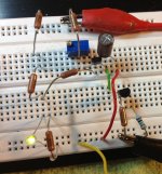
I am installing these components in a pair of perf boards for testing in my DDDAC board. If the Rakk DAC guys do this with 2 transistors then we can too.
Anyone willing to Spice test a simulation of this circuit?
I breadboard tested a two transistor CCS circuit and came up with resistor values that provided 0.4ma from a source varying around 2.4v. The current regulating JFET source resistor only drops the voltage about .337v so that leaves just over 2 volts drop for the two transistors. A base voltage to the ZTX450 was provided by a green LED running at 4ma which roughly divides the voltage drop in half across the two transistors. According to data sheets Both the ZTX450 and 2SK170 can operate stably at voltage drops well below 1vdc.
I simulated pin 20 with a variable resistor. The constant current circuit is rock steady over a wide range of voltages. Running the "pin 20" voltage up to 4.0 volts shows no measurable change in current. The "pin 20" voltage was dropped as low as 1.4vdc before the current was reduced by 0.1%.
I am installing these components in a pair of perf boards for testing in my DDDAC board. If the Rakk DAC guys do this with 2 transistors then we can too.
Anyone willing to Spice test a simulation of this circuit?
Attachments
I breadboard tested a two transistor CCS circuit and came up with resistor values that provided 0.4ma from a source varying around 2.4v. The current regulating JFET source resistor only drops the voltage about .337v so that leaves just over 2 volts drop for the two transistors. A base voltage to the ZTX450 was provided by a green LED running at 4ma which roughly divides the voltage drop in half across the two transistors. According to data sheets Both the ZTX450 and 2SK170 can operate stably at voltage drops well below 1vdc.
I simulated pin 20 with a variable resistor. The constant current circuit is rock steady over a wide range of voltages. Running the "pin 20" voltage up to 4.0 volts shows no measurable change in current. The "pin 20" voltage was dropped as low as 1.4vdc before the current was reduced by 0.1%.
I am installing these components in a pair of perf boards for testing in my DDDAC board. If the Rakk DAC guys do this with 2 transistors then we can too.
Anyone willing to Spice test a simulation of this circuit?
great work
I breadboard tested a two transistor CCS circuit and came up with resistor values that provided 0.4ma from a source varying around 2.4v. The current regulating JFET source resistor only drops the voltage about .337v so that leaves just over 2 volts drop for the two transistors. A base voltage to the ZTX450 was provided by a green LED running at 4ma which roughly divides the voltage drop in half across the two transistors. According to data sheets Both the ZTX450 and 2SK170 can operate stably at voltage drops well below 1vdc.
I simulated pin 20 with a variable resistor. The constant current circuit is rock steady over a wide range of voltages. Running the "pin 20" voltage up to 4.0 volts shows no measurable change in current. The "pin 20" voltage was dropped as low as 1.4vdc before the current was reduced by 0.1%.
I am installing these components in a pair of perf boards for testing in my DDDAC board. If the Rakk DAC guys do this with 2 transistors then we can too.
Anyone willing to Spice test a simulation of this circuit?
Not today, but I will spice this one and run some variations of the RC filter, specially as you are now introducing the 8 volt supply back to the bias, good to know what the rejection is there....
the current diodes are basically a very elegant way to tweak here. one component versus another...
at the end the ears must decide 😀
great work guys,
dunno bout you guys but current diodes with 400uA are a little hard to come by here
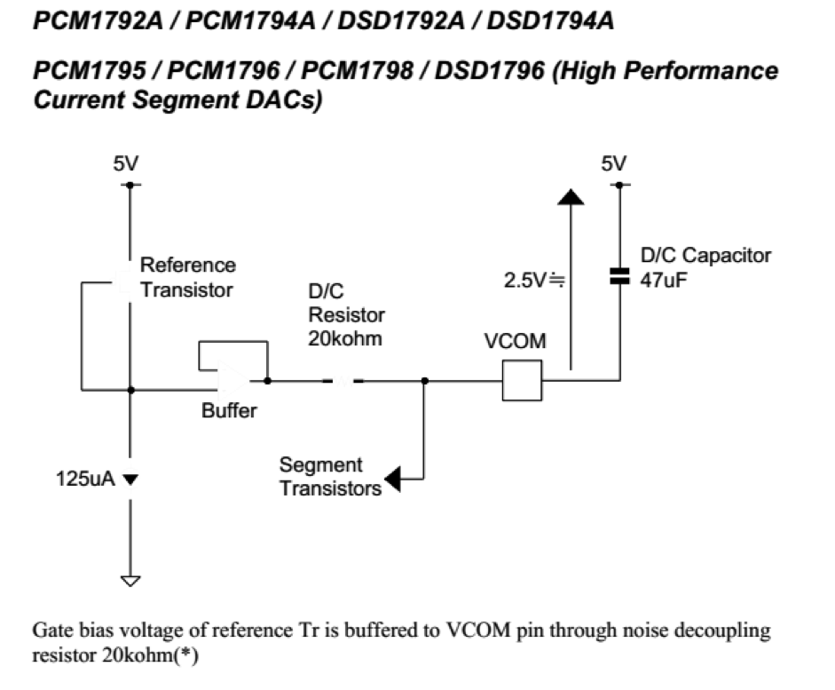
deviation from 400uA moves vcom voltage, pin 20 v, and output bias v
jfet ccs should be better?
dunno bout you guys but current diodes with 400uA are a little hard to come by here
deviation from 400uA moves vcom voltage, pin 20 v, and output bias v
jfet ccs should be better?
Top work Ross!
It looks like quite a high component count, but I guess if a little board's made and surface mount components were used it needn't take up much room.
How does a solution like this compare to using something like a Burr Brown REF200, which it seems could be pinned to give a load of 400uA from a single component with no requirement for being powered?
....
How does a solution like this compare to using something like a Burr Brown REF200, which it seems could be pinned to give a load of 400uA from a single component with no requirement for being powered?
..Looks intresting, very accurate (100uA +/- 0.5%), avaliable in mini DIP & SOIC package.
Something like this (?):
An externally hosted image should be here but it was not working when we last tested it.
Last edited:
Yeah, exactly. Plus one of these type of things and it'd be fairly simple to make something that can go in place of the resistor on the board..Looks intresting, very accurate.
Something like this (?):
An externally hosted image should be here but it was not working when we last tested it.
An externally hosted image should be here but it was not working when we last tested it.
An externally hosted image should be here but it was not working when we last tested it.
It would certainly make it straightforward to implement this solution in a neat and efficient way.
But is this ref200 IC likely to be as precise and effective as a discrete solution like a jfet cascode ccs?
But is this ref200 IC likely to be as precise and effective as a discrete solution like a jfet cascode ccs?
as I wrote before - neg rail is way to go ; say , everything from -5V ...
even if "dirty" one (unregged) will do the job , due to CCS isolation
Dear Mighty ONE!
Would you suggest to us an implementation of the negative rail CCS?
With awe and gratitude!
on the REF200 400uA setup through mirror... compliance is 4 volt, so won't work, as max compliance will be the 2.4 volt... unless you take a negative rail. ergo, not easy to implement.....
I also think 8 parts for the FET solution is a bit much....
why not parallel two of the current regulator diodes? this will give you 400uA
I also think 8 parts for the FET solution is a bit much....
why not parallel two of the current regulator diodes? this will give you 400uA
Dear Mighty ONE!
Would you suggest to us an implementation of the negative rail CCS?
With awe and gratitude!

to reply here , while preparing proper e-mail reply to you
pretty much the same as already posted in http://www.diyaudio.com/forums/digi...pcm1794-waveio-usb-input-131.html#post4039198 , except possible inclusion of generic green led in T2 emiter , thus demanding increased R2
regarding neg rail ...... having free secondary ( & graetz + cap) is trivial ..... or using any neg rail , possible existing in system , for output buffer or something .......
I'm interested in this ddac , but will go pure balanced xformer based I/V route , so - one deck and additional gain stage with bipolar supply are logical way to go
Last edited:
Could paralleling current diodes be akin to parallel batteries or transformers?
I would not want to do that.
Unfortunately, since the above would be easy and convenient, I suspect the discrete approach will be superior for reasons of noise generation as much as any other reason.
I am excited that Prodanovic has joined the discussion. One of the great men of DIY audio - wish I knew one one-hundredth of the knowledge he has at the tip of his tongue and the skills of his fingertips.
We were writing at the same time.
I guess I am confused as to where the negative supply comes in.
You could not possibly forget you are dealing with a dilettante!
Make it plain for us whose enthusiasm exceeds out knowledge, please.
I guess I am confused as to where the negative supply comes in.
You could not possibly forget you are dealing with a dilettante!
Make it plain for us whose enthusiasm exceeds out knowledge, please.
We were writing at the same time.
I guess I am confused as to where the negative supply comes in.
You could not possibly forget you are dealing with a dilettante!
Make it plain for us whose enthusiasm exceeds out knowledge, please.
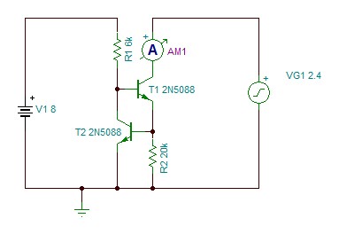
say like this
8V is additional small PS
6K8 - series connection of 5K6 fixed and 2K trimmpot - at least for test ; later can be substituted with fixed , proper value
Attachments
Ah, Zen Mod in the DDDAC1794 thread...welcome 
I'm very curious for your implementation.....
The DDDAC I have build with four boards and Cinemag output trafos is already a wonderful DAC
Walter
I'm very curious for your implementation.....
The DDDAC I have build with four boards and Cinemag output trafos is already a wonderful DAC
Walter
Could paralleling current diodes be akin to parallel batteries or transformers?
I would not want to do.
these are current sources, so that is the same as putting batteries in series.... so it can be done without any issue.... remember the dddac does exactly the same, paralleling the outputs, which are basically current sources 😀
I'm still really intrigued that k&k with their mkIV rakk dac have a solution for this pin20 current reference which
1) doesn't appear to use a load of discrete components
2) doesn't need a separate negative power supply feed
3) they described as "an innovative design that took quite a bit to develop"
1) doesn't appear to use a load of discrete components
2) doesn't need a separate negative power supply feed
3) they described as "an innovative design that took quite a bit to develop"
- Home
- Source & Line
- Digital Line Level
- A NOS 192/24 DAC with the PCM1794 (and WaveIO USB input)