BSP 135 is small depletion mode mosfet ,meaning that biasing is same as with JFet ( depletion biasing also) and triode 
so - gate resistor is suppression - ( antiosc) , and source resistor is biasing
anyway ... another possibility , if 2V4 as voltage window and dipole CCS is your poison
so - gate resistor is suppression - ( antiosc) , and source resistor is biasing
anyway ... another possibility , if 2V4 as voltage window and dipole CCS is your poison
BSP 135 is small depletion mode mosfet ,meaning that biasing is same as with JFet ( depletion biasing also) and triode
so - gate resistor is suppression - ( antiosc) , and source resistor is biasing
anyway ... another possibility , if 2V4 as voltage window and dipole CCS is your poison
The problem I have with the depletion mode FET is the wide variety of bands they come in. the suggested 1 volt is at the corner of the ID/ VGS curve, meaning, the FET just starts to conduct at that point. This 1 volt is a very crude average... they come in6 or 7 bands and the delta is huge
so the VGS where the 400uA runs, might be 0,8 volt or 1,2 volt, also depending on temperature. or even further off. selection is needed to start with and than still....
this means my carefully designed DC bias points which are ROCK solid at 2,7 volt will drift with the same variation. unacceptable... if you want this you need a trimmer at the resistors position or use a DC servo mechanism. All possible, no problem, but far from simple.... like the negative rail. good for one board, but not for multiple boards. Than I would prefer a BJT as the VGE is much more constant....
I ordered some of the current diodes. I wanted to have an idea of the audible differences in my test /tweak DAC to compare to the stock DAC... I also ordered some of the new series of Panasonic SEQP oscons... I see again quite some combinations to listen to 😉
CCS Boards Installed in DDDAC
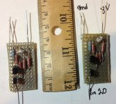
I built a couple of CCS boards and installed them in my fully tweaked DDDAC board in place of the 6K resistor. The CCS sound is different compared with the 6K resistor. My first reaction is that the music is more forward with more energy - especially in the midrange and bass. Also there is more ambient sound and better instrument/voice separation. Complex treble material congests a bit and bad recordings sound worse, but this could be "new parts sound". The 6K resistor sound is slightly more compressed by comparison.
Measurements at pin 20 are: current = 0.41ma and volts = 2.44. Rload is 2.9 volts.
I will let the DDDAC play 24hours/day for the next 3-4 days for the components to break in. I want to check for long term listenablilty and musicality next. New components always have an "unsettled" sound which should disappear with time. I will then put the 6k resistor back in the circuit for comparison.
The CCS circuit would be 1/4 the size of the test boards using SMD resistors. It will also need a pot to adjust for exactly 0.400ma or 2.40V at pin 20 or 2.7V into 133 ohm load resistors, or whatever the magic number happens to be. This would also accommodate unsorted JFETS.
I hope someone is testing a super premium resistor such as a Rhopoint or TX2575 to pin 20. I find the quality of load resistors always affect total sound quality. This will work on board stacks whereas the CCS with pot can only be easily implemented on a single board DDDAC.
Attachments
I had a similar change in sound with the current diodesI built a couple of CCS boards and installed them in my fully tweaked DDDAC board in place of the 6K resistor. The CCS sound is different compared with the 6K resistor. My first reaction is that the music is more forward with more energy - especially in the midrange and bass. Also there is more ambient sound and better instrument/voice separation. Complex treble material congests a bit and bad recordings sound worse, but this could be "new parts sound". The 6K resistor sound is slightly more compressed by comparison.
Measurements at pin 20 are: current = 0.41ma and volts = 2.44. Rload is 2.9 volts.
I will let the DDDAC play 24hours/day for the next 3-4 days for the components to break in. I want to check for long term listenablilty and musicality next. New components always have an "unsettled" sound which should disappear with time. I will then put the 6k resistor back in the circuit for comparison.
The CCS circuit would be 1/4 the size of the test boards using SMD resistors. It will also need a pot to adjust for exactly 0.400ma or 2.40V at pin 20 or 2.7V into 133 ohm load resistors, or whatever the magic number happens to be. This would also accommodate unsorted JFETS.
I hope someone is testing a super premium resistor such as a Rhopoint or TX2575 to pin 20. I find the quality of load resistors always affect total sound quality. This will work on board stacks whereas the CCS with pot can only be easily implemented on a single board DDDAC.
More lively more clarity and better bass
Anyway I had z foils in previous which I thought was marginally better than the stock resistor
Can't see from those pics, but are your RCAs grounded to the chassis? best if they're not.
Also, are you using a WaveIO? If so, there's one of the mounting holes which you don't want to connect to the metal chassis as it's a grounding point. It's the one with the ground symbol by it.
Does the hum change if your Cinemags aren't sat on the metal chassis?
Worth a quick look at these bits, humming often means you have a grounding issue.
I'm all sorted now chaps! i looked over the DAC many times and it was all wired as it should be. I had the mad idea of taking out my valve pre amp and putting an old passive amp in place, and the loud hum instantly went! I don't know how I developed a pre amp problem at exactly the same time as I installed the cinemas in my DAC? Very odd, I'll get the valve pre looked at.
THANKS JAMES AND DOEDE FOR YOUR HELP!
Unless by using a passive pre amp (with no connection to the mains) the passive pre amp is not highlighting a grounding issue with the DDDAC? I will be taking my DDDAC to a DAC bake off using someone elses hi fi. If the DDDAC hums in another hifi system then we Know its the DDDAC and not my valve pre
Not today, but I will spice this one and run some variations of the RC filter, specially as you are now introducing the 8 volt supply back to the bias, good to know what the rejection is there....
For the biased CCS I posted ("three legged"), rejection should be around 130dB for most of the audio band, decreasing to under 110dB over 40kHz. Not sure how critical high frequency performance is, this being a DAC. But all CCSs do best in some range and less well in others.
I'm also pretty sure this rejection applies both to signal injected in the current regulating circuit, and to the CCSs supply ("bias") itself. But more thought should be put in this difference.
The current regulating diodes should reject pretty close to 120dB and not offer the complication of injecting PS noise in pin 20. But not biasing the CCS restricts the options a lot.
I built a couple of CCS boards and installed them in my fully tweaked DDDAC board in place of the 6K resistor. The CCS sound is different compared with the 6K resistor. My first reaction is that the music is more forward with more energy - especially in the midrange and bass. Also there is more ambient sound and better instrument/voice separation. Complex treble material congests a bit and bad recordings sound worse, but this could be "new parts sound". The 6K resistor sound is slightly more compressed by comparison.
Measurements at pin 20 are: current = 0.41ma and volts = 2.44. Rload is 2.9 volts.
I will let the DDDAC play 24hours/day for the next 3-4 days for the components to break in. I want to check for long term listenablilty and musicality next. New components always have an "unsettled" sound which should disappear with time. I will then put the 6k resistor back in the circuit for comparison.
The CCS circuit would be 1/4 the size of the test boards using SMD resistors. It will also need a pot to adjust for exactly 0.400ma or 2.40V at pin 20 or 2.7V into 133 ohm load resistors, or whatever the magic number happens to be. This would also accommodate unsorted JFETS.
I hope someone is testing a super premium resistor such as a Rhopoint or TX2575 to pin 20. I find the quality of load resistors always affect total sound quality. This will work on board stacks whereas the CCS with pot can only be easily implemented on a single board DDDAC.
Nice work, thanks 🙂
I did some work on the spice simulation and was a bit surprised, that the cascode transistor had no real influence on the output impedance of the current source.
In summary:
0-100kHz 4Mohm – 2M
1MHz 50k
10MHz 6k
For the audio band VERY good, for the digital noise till 10MHz better than a 6k resistor 😉
It feels "only a FET" would be sufficient…. Easier to build,
Still the trimming or selecting would be a point…
But a FET, one R and a trimmer is not a big deal of course
Carlsor, would you like to try this?
I suggest using a 2N4338 selected for enough Idss for this, due to its suitable Vgs(off) for best performance (see literature). It's really critical to keep as far from Vgs(off) as possible. I think nige2000 has the part - done, tried, listened to?... Let us know. I think you were close to trying it out.
I couldn't find a better JFET than that one per given req's, though if anybody comes up with a better part... Awesome.
So that are my thoughts on the selecting part. As far as trimming goes, due to variations of JFETs manufacture, the kits may include preselected JFETs, maybe the PCB could be ajusted to include a trim pot for selecting an optimal Iset before full DAC fire up, and a fixed series R to limit the range. But I'm just maybe thinking a bit too far ahead.
2n4338 has 340 uA at Zero volt UGS, so that is too low.... Will be interesting to find a table or selector guide with FETs with Ids at UGS=0volt.... I will check, hope some otters will have some idea too 🙂
Last edited:
I posted this link before, not sure if you guys saw it. This page shows some intresting examples of small size CCS pcb's
https://mrevil.asvachin.eu/electronics/modules/#jfet_ccs
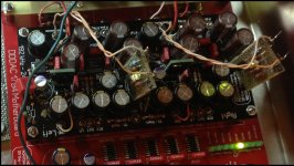
Btw I installed 8x Tentlab 8v shunts. I now understand what all the fuss is about.. 😀😀😀
I also rewired the unregulated ps to create space for the imminent arrival of the highly anticipated new BBB audio Cape, (I've not been able to order it yet either)
https://mrevil.asvachin.eu/electronics/modules/#jfet_ccs
Btw I installed 8x Tentlab 8v shunts. I now understand what all the fuss is about.. 😀😀😀
I also rewired the unregulated ps to create space for the imminent arrival of the highly anticipated new BBB audio Cape, (I've not been able to order it yet either)
An externally hosted image should be here but it was not working when we last tested it.
Last edited:
2n4338 has 340 uA at Zero volt UGS, so that is too low.... Will be interesting to find a table or selector guide with FETs with Ids at UGS=0volt.... I will check, hope some otters will have some idea too 🙂
😀 that went quick.... used digikey selector guide in their iPad app. 2N4339 will do, J113 and BF244A. all need a resistor between source and GND, but it will run just about at the right voltage.
the proof will be in the eating of course.....
Stijn, I suggest you remove the screw on the WaveIO board where the GND is connected at the corner. As you have it now, your WaveIO GND, hence computer GND is connected to your chassis. I am sure you do not want that? refer to the pictures at my web site on the USB section, the part where you see the bottom picture. it is described there in detail
instead of Jfet , it's possible to use this http://www.ti.com/general/docs/lit/getliterature.tsp?genericPartNumber=lm134&fileType=pdf
....
Hi Doede, thanks, I'm using plastic stand-off spacers for the WaveIO board. 🙂
Last edited:
the proof will be in the eating of course.....
"Eating"!? Should we be concerned? ;-)
Simple JFET CCS
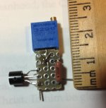
I tested a simple adjustable JFET CCS circuit using a 2SK170. Attached is a picture of one I constructed. Doede, like the parts count? Breadboard testing showed that the gate resistor is not needed. A fixed 470 ohm resistor and a 500 ohm pot should work. The 2SK369 and 2SK117 should be suitable alternative JFETS. It is simple and small enough for anyone to build. The 2SK170 and the other JFETs are available on eBay. The main issue is that the 6K resistor is closely surrounded with tall components, so solder access is an issue.
I did a dynamic test with .5v signals imposed on 2.4V to the circuit. The scope showed resultant voltage signal variations of 2.2mv across the 709 ohm source resistor as compared to 0.2mv for the 2 transistor CCS. The signal looked clean. This represents a current variation of about 0.8%. Does Spice simulation provide the types and amounts of distortion expected for these two CCS circuit designs? Supposedly JFETs have even order distortion which is pleasing.
I will wait to see how the 2 transistor CCS sounds after 100 hours of break-in time before I insert the simple JFET boards.
Attachments
Last edited:
- Home
- Source & Line
- Digital Line Level
- A NOS 192/24 DAC with the PCM1794 (and WaveIO USB input)