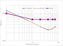
Using the SMPS, the maxi power at 4 ohm is 75W.
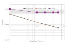
In the figure, it is the compare with TI PA100 amp. Even using my primitive test gears and power supply, the amp has better THD+N than TI PA100.
The measured THD+N is approaching the limits of the Solo 3rd, these numbers might be mainly caused by the Solo 3rd itself.
In the figure, it is the compare with TI PA100 amp. Even using my primitive test gears and power supply, the amp has better THD+N than TI PA100.
The measured THD+N is approaching the limits of the Solo 3rd, these numbers might be mainly caused by the Solo 3rd itself.
Attachments
Last edited:
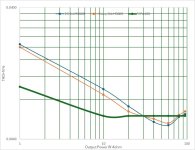
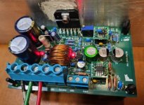
Using 600W, 120/double 24VAC toroidal transformer, 140,000uF CRC smoothing, at +/-32VDC, the maximal output power is 95W at 4 ohm.
The THD+N at lower power level is much higher than TI figures because of noise. But above 30W, it has less THD+N than TI PA100.
The THD+N at lower power level is much higher than TI figures because of noise. But above 30W, it has less THD+N than TI PA100.
Attachments


This is my understanding. It could be wrong.
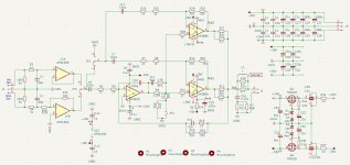
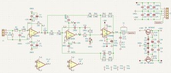
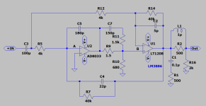
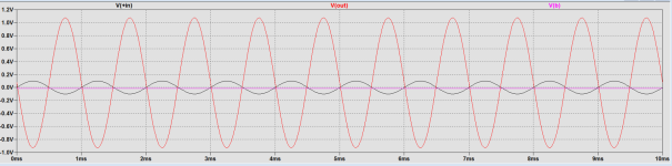
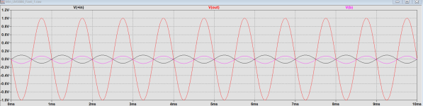
Monitoring V(b) at +in of LM3886 of EC amp, it is very low. I think it is only the error signal.
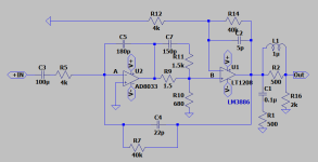
But for Comp amp, it is almost equal to the input signal.
Monitoring V(b) at +in of LM3886 of EC amp, it is very low. I think it is only the error signal.
But for Comp amp, it is almost equal to the input signal.
Attachments
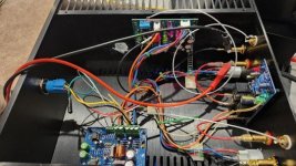
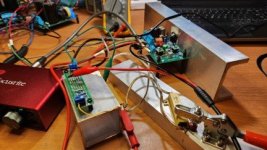
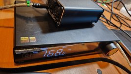
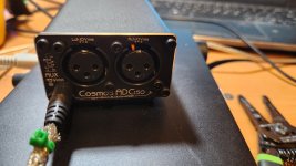
New toys.
Topping E70 DAC and Cosmos ADCiso.
Topping THD+N: OEM (XLR) 0.00008%, Audiosciencereview 0.000094%
ADCiso(B): THD+N: Audiosciencereview 0.000098-0.000138%
My setting up:
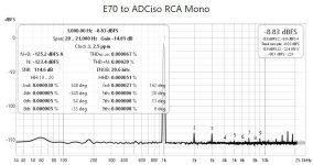
Topping RCA -> ADCiso 2.5mm mono: 0.0002%
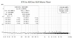
Topping XLR -> ADCiso XLR mono: 0.000091%
On par with OEM and some reviewers.
Topping E70 DAC and Cosmos ADCiso.
Topping THD+N: OEM (XLR) 0.00008%, Audiosciencereview 0.000094%
ADCiso(B): THD+N: Audiosciencereview 0.000098-0.000138%
My setting up:
Topping RCA -> ADCiso 2.5mm mono: 0.0002%
Topping XLR -> ADCiso XLR mono: 0.000091%
On par with OEM and some reviewers.
Attachments

Measurements:
On par with Modulus-286.
The biggest problem is that my tests show a very high background noise at 60Hz. This might be caused by the power supply and my SE buffer at the input( compare to Tom's balanced input buffer)
On par with Modulus-286.
The biggest problem is that my tests show a very high background noise at 60Hz. This might be caused by the power supply and my SE buffer at the input( compare to Tom's balanced input buffer)
Attachments


Congrats on your Cosmos ADCiso purchase, game changer regarding measurements
I would also expect Modulus to have less distortion due to it's balanced input. Any listening test yet ?
I would also expect Modulus to have less distortion due to it's balanced input. Any listening test yet ?
I have been listening to the amp for months. I can't hear any difference.
They are very similar sound, pure and straight.
It is my personal subjective feeling that the EC mode sounds a little bit more rounded in high if you put your ears close to tweeter. It might to be its H2 dominance than the comp mode.
They are very similar sound, pure and straight.
It is my personal subjective feeling that the EC mode sounds a little bit more rounded in high if you put your ears close to tweeter. It might to be its H2 dominance than the comp mode.
It looks to me that the data presented on fig.179 in post #49 and fig. "EC 1655 40W4Ohm" in post #45 are contradictory.
Can you please comment on this.
Can you please comment on this.
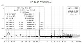
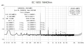
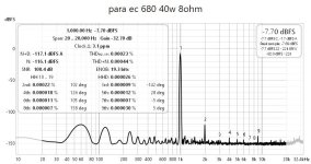
#45, single LM3886 EC amp measurement with old Focusrite Solo 3rd.
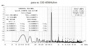
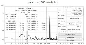
#49, EC/Comp 2xLM3886 amp measured with the new ADCiso.
#49, EC/Comp 2xLM3886 amp measured with the new ADCiso.
It does not look very convincing.#45, single LM3886 EC amp measurement with old Focusrite Solo 3rd.
#49, EC/Comp 2xLM3886 amp measured with the new ADCiso.
Here is why:
The 3rd harmonic in the picture EC 1654 40W4Ohm in post #45 is 0.000086%. And you said that is was measured using Focusrite Solo 3.
The picture EC/Comp 2xLM3886 in post #49 shows the third harmonic to be 0.000063%.
The difference between these two is 0.000023%
This is impossible as this means that Focusrite and the difference in the amps itself have contributed 0.000023%.
BUT this audio interface alone has much higher 3rd harmonic, around 30dB higher.
How would you explain that?
I don't know how low Focusrite can measure 3rd harmonic. I know total THD+N is 0.002%.
I also don't know any ADC has separate spec on 2nd, 3rd, 4th measurement.
I can't answer your question.
I also don't know any ADC has separate spec on 2nd, 3rd, 4th measurement.
I can't answer your question.
Last edited:
You can measure the Focusrite THD, you have:I don't know how low Focusrite can measure 3rd harmoni
Topping E70 DAC and Cosmos ADCiso
@Gonkar : "The difference between these two is 0.000023% ... Focusrite and the difference in the amps itself have contributed 0.000023%"
This isn't how harmonic distortion adds up.
For example you can have measurement equipment with 1% 3rd harmonic distortion and a device-under test (DUT) with 1% 3rd harmonic and together they can measure 0%! Why? Because if the phase of the 3rd harmonic of one of the devices is 180 degrees relative to the other, that frequency component will cancel out and you will measure 0.
This is why as a rule-of-thumb the measurement equipment must be an order of magnitude better than the DUT, otherwise you can't separate the measurement of the DUT from that of the measurement equipment.
yes, but the difference is the much higher open loop gain of composite amp. Thus the error correction potential of negative feedback increases.Is it just negative feedback applied, or something else?
The challenge is to still keep the amp stable.
I'm sorry but I can agree with that assumption.For example you can have measurement equipment with 1% 3rd harmonic distortion and a device-under test (DUT) with 1% 3rd harmonic and together they can measure 0%! Why? Because if the phase of the 3rd harmonic of one of the devices is 180 degrees relative to the other, that frequency component will cancel out and you will measure 0.
First, why there should be phase difference.
Second, the odd harmonics don't cancel each other. In some cases even harmonics can be canceled but not the odd ones. The even and odd harmonics represent different non-linearity.
I completely agree with that but not because of the argument in the first part of your post.This is why as a rule-of-thumb the measurement equipment must be an order of magnitude better than the DUT, otherwise you can't separate the measurement of the DUT from that of the measurement equipment.
Not correct. When you have odd harmonics from, say, a symmetic expanding transfer function then a symmetric but inversly compressing transfer function can cancel it. This no different than with even order harmonics.Second, the odd harmonics don't cancel each other.
Code:
Fourier components of V(out1)
Harmonic	Frequency	 Fourier 	Normalized	 Phase  	Normalized
 Number 	  [Hz]   	Component	 Component	[degree]	Phase [deg]
    1   	 1.000e+3	 1.196e+0	 1.000e+0	  -89.96°	    0.00°
    2   	 2.000e+3	 6.426e-9	 5.373e-9	  -83.83°	    6.13°
    3   	 3.000e+3	 4.345e-1	 3.633e-1	   90.25°	  180.21°
    4   	 4.000e+3	 1.280e-8	 1.070e-8	  -86.22°	    3.74°
    5   	 5.000e+3	 2.326e-1	 1.945e-1	  -89.45°	    0.51°
    6   	 6.000e+3	 1.917e-8	 1.603e-8	  -86.72°	    3.24°
    7   	 7.000e+3	 9.247e-2	 7.733e-2	   91.18°	  181.14°
    8   	 8.000e+3	 2.553e-8	 2.135e-8	  -86.74°	    3.22°
    9   	 9.000e+3	 2.761e-2	 2.309e-2	  -87.35°	    2.61°
Total Harmonic Distortion:   41.994570%

Fourier components of V(out2)
Harmonic	Frequency	 Fourier 	Normalized	 Phase  	Normalized
 Number 	  [Hz]   	Component	 Component	[degree]	Phase [deg]
    1   	 1.000e+3	 5.999e-1	 1.000e+0	   90.03°	    0.00°
    2   	 2.000e+3	 6.432e-9	 1.072e-8	   96.64°	    6.61°
    3   	 3.000e+3	 1.146e-4	 1.910e-4	    0.73°	  -89.30°
    4   	 4.000e+3	 1.280e-8	 2.134e-8	   93.99°	    3.97°
    5   	 5.000e+3	 1.119e-4	 1.866e-4	 -178.00°	 -268.03°
    6   	 6.000e+3	 1.918e-8	 3.197e-8	   93.40°	    3.37°
    7   	 7.000e+3	 6.771e-5	 1.129e-4	    2.60°	  -87.43°
    8   	 8.000e+3	 2.554e-8	 4.257e-8	   93.33°	    3.30°
    9   	 9.000e+3	 2.613e-5	 4.355e-5	 -177.01°	 -267.04°
Total Harmonic Distortion:   0.028444%
EDIT: And as soon as you have some measurement experience you will see this (partial) cancelling of some of even or odd harmonics happens all the time, typically from the ADC having the inverse error that the DAC at specific levels and frequencies.
- Home
- Amplifiers
- Chip Amps
- A New EC-Composite LM3886 Amp