You don't need to worry.Tell me please, when I use REW to do FFT, does it take an integral number of cycle by using 192KHz sample rate, 64k length, average 8?
Just select a proper window function for the FFT (like Cosine-Sum 235).
I also suggest 256k FFT size, maximum overlap and 32 averages, and 96kHz should suffice. Also, it's a good idea to reset the averaging after some time (some 10's of seconds), to allow the system to settle first, notably important when AC-coupled (as the abrupt start of a sine generates a DC component whose decay trail affects the harmonics seen).
There is a option in the generator "Lock Frequency to RTA FFT" which adjusts the frequency to the nearest bin center (to achieve that integral multiple of cycles within one FFT block) but that option is only needed if you a) have no window (aka rectangular) applied and b) the recording is sample-synced to the playback, DAC and ADC running from the same local clock in a soundcard.
Having this option engaged all the time is still good idea as the amplitude precision is better and independent of window function (assuming sample-synced record).

I've been building chip amplifiers and even simple discrete circuits for over 30 years, albeit with only a limited knowledge.
I'm actually a qualified restorer of paintings, sculptures, and murals. Because of my love of audio electronics, I sought another apprenticeship in 2003, but unfortunately, I only found one as a mechatronics engineer for automation technology. It was better than nothing, and I thought I'd definitely be able to build my own CD player after the apprenticeship, but that wasn't the case. In the end, after my apprenticeship, I knew a bit about PLC programming, milling, turning, motors of all kinds, and hydraulics. Electronics, especially analog circuits, weren't covered in any of the learning areas, so I've continued to be self-taught to this day!
I've always been satisfied with my self-built devices, but I've always used purchased devices as my main system.
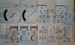
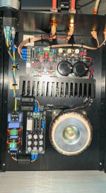
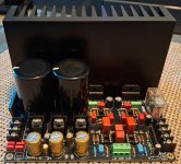
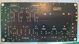
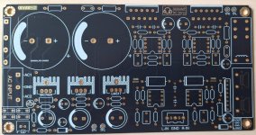
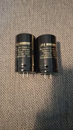
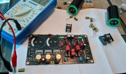
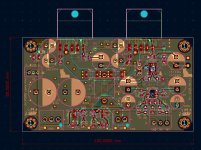
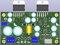
That's changed, though, since I built my last amplifier with the LM3886. By chance, I got a circuit board called DC-Servo from a private seller. It looks very similar to the boards with the Cirmech logo that are sold on eBay and AliExpress. After weeks of research, I acquired a component layout plan, which differs considerably from the one shown on Alibaba for the Cirmech boards. I got all the components and measured them to an accuracy of less than 1%. Because it is a stereo amplifier, I paired the components for the left and right sides exactly. I used two OPA1655s as operational amplifiers and the OPA277 for the DC servo. I had soldered DIP adapters onto the board from the start so that I could test different operational amplifiers. I soldered in two Mundorf Mlytic 15000uF as the main electrolytic capacitors in the power supply, and Nichicon fine gold electrolytic capacitors for the voltage regulation for the operational amplifiers. All resistors are Vishay CMF55, CMF60, or Wellwyn metal film resistors. I used 10uF Wima MKS electrolytic capacitors for the operational amplifier. All small high-frequency filter capacitors in the signal are either Wima FKP or Roederstein KP capacitors. I also replaced the small 100nF capacitors used for noise suppression on the operational amplifiers with 1uF Wima MKS capacitors. Below the circuit board, I connected a 100nF X7R capacitor in parallel with all the capacitors in the circuit. I'm attaching photos of the amplifier and the component diagram to this post. Can anyone explain exactly what I've built and why it always sounds better than my Naim Nait 5si when used with several different speakers? The sound is just as dynamic and solid as the Naim, even at higher volumes, but much more transparent, spacious, and natural.
I'm actually a qualified restorer of paintings, sculptures, and murals. Because of my love of audio electronics, I sought another apprenticeship in 2003, but unfortunately, I only found one as a mechatronics engineer for automation technology. It was better than nothing, and I thought I'd definitely be able to build my own CD player after the apprenticeship, but that wasn't the case. In the end, after my apprenticeship, I knew a bit about PLC programming, milling, turning, motors of all kinds, and hydraulics. Electronics, especially analog circuits, weren't covered in any of the learning areas, so I've continued to be self-taught to this day!
I've always been satisfied with my self-built devices, but I've always used purchased devices as my main system.
That's changed, though, since I built my last amplifier with the LM3886. By chance, I got a circuit board called DC-Servo from a private seller. It looks very similar to the boards with the Cirmech logo that are sold on eBay and AliExpress. After weeks of research, I acquired a component layout plan, which differs considerably from the one shown on Alibaba for the Cirmech boards. I got all the components and measured them to an accuracy of less than 1%. Because it is a stereo amplifier, I paired the components for the left and right sides exactly. I used two OPA1655s as operational amplifiers and the OPA277 for the DC servo. I had soldered DIP adapters onto the board from the start so that I could test different operational amplifiers. I soldered in two Mundorf Mlytic 15000uF as the main electrolytic capacitors in the power supply, and Nichicon fine gold electrolytic capacitors for the voltage regulation for the operational amplifiers. All resistors are Vishay CMF55, CMF60, or Wellwyn metal film resistors. I used 10uF Wima MKS electrolytic capacitors for the operational amplifier. All small high-frequency filter capacitors in the signal are either Wima FKP or Roederstein KP capacitors. I also replaced the small 100nF capacitors used for noise suppression on the operational amplifiers with 1uF Wima MKS capacitors. Below the circuit board, I connected a 100nF X7R capacitor in parallel with all the capacitors in the circuit. I'm attaching photos of the amplifier and the component diagram to this post. Can anyone explain exactly what I've built and why it always sounds better than my Naim Nait 5si when used with several different speakers? The sound is just as dynamic and solid as the Naim, even at higher volumes, but much more transparent, spacious, and natural.
Attachments
-
 20250526_101453.jpg402.7 KB · Views: 130
 -
 20250518_160622(1).jpg607.5 KB · Views: 128
 -
 20250512_150039.jpg567.9 KB · Views: 116
 -
 20250427_104806.jpg586.7 KB · Views: 121
 -
 20250426_184719.jpg302.7 KB · Views: 119
 -
 20250426_172540.jpg460.9 KB · Views: 116
 -
 20250423_151409.jpg424.7 KB · Views: 115
 -
 20250501_070817.jpg459.4 KB · Views: 117
 -
 20250426_172540.jpg460.9 KB · Views: 128
Nice!
How is it measured?
I built Naim before.
After I litsened the 6xLM3886 amp, I won't build class AB amp unless there is a new topology or charactoristics in sound.
It is so pure.
How is it measured?
I built Naim before.
After I litsened the 6xLM3886 amp, I won't build class AB amp unless there is a new topology or charactoristics in sound.
It is so pure.
I tried the following op amps:
OPA1655
OPA1641
OPA1611
OPA1611+ClassA (China, AliExpress)
OPA134
Sparkos SS3601
Burson Audio S7vivid pro single
Burson Audio V6
OPA627 single version
NE5534
The OPA1611+ClassA has by far the best sound, but because several op amps in the shipment were defective, I decided against it.
The second best is the OPA1655, although the OPA1611 sounded a bit more natural, but lackluster.
NO measurementNice!
How is it measured?
I built Naim before.
After I litsened the 6xLM3886 amp, I won't build class AB amp unless there is a new topology or charactoristics in sound.
It is so pure.
OpA1611+ClassAIch habe die folgenden Operationsverstärker ausprobiert:
OPA1655
OPA1641
OPA1611
OPA1611+ClassA (China, AliExpress)
OPA134
Sparkos SS3601
Burson Audio S7vivid pro single
Burson Audio V6
OPA627 Einzelversion
NE5534
Der OPA1611+ClassA hat zwar mit Abstand den besten Klang, da in der Lieferung aber mehrere Operationsverstärker defekt waren, habe ich mich dagegen entschieden.
Der zweitbeste ist der OPA1655, obwohl der OPA1611 etwas natürlicher, aber glanzloser klang.
https://a.aliexpress.com/_EQnc3qE
OPA2828 has a different package. I liked to try it but didn't.
The OPA2828 is a dual operational amplifier, the single version is the OPA828, sound very similar to the OPA627

- Home
- Amplifiers
- Chip Amps
- A New EC-Composite LM3886 Amp