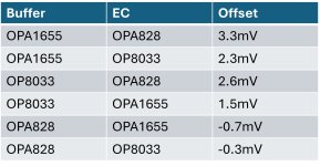
DC Offset
With capacitor C7 in place, the DC offset baseline is approximately 1.1 mV.
By bypassing C7, the amplifier becomes fully DC-coupled.
However, op-amps with BJT inputs are not suitable for this DC-coupled configuration due to unbalanced resistance and higher bias currents. For example, if C7 is bypassed, the OPA891 at the error correction (EC) stage produces about 0.1 V of DC offset. When used as a buffer, this offset can approach 1 VDC.
The best DC offset performance is achieved when using the OPA828 in the buffer stage.
If a few millivolts of DC offset are acceptable, the EC LM3886 can operate as a DC-coupled amplifier. This approach can be especially appealing to DIY enthusiasts who prefer signal paths without capacitors.
Attachments

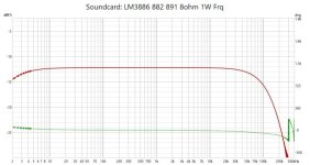
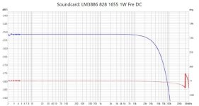
Frequency Response
There is no noticeable difference at high frequencies. However, at the low-frequency end, a difference becomes apparent — indicating that the amplifier now operates as a DC-coupled amp.
There is no noticeable difference at high frequencies. However, at the low-frequency end, a difference becomes apparent — indicating that the amplifier now operates as a DC-coupled amp.
Attachments
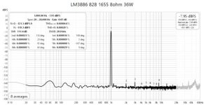
THD+N at 36W into 8Ω
(OPA828 as buffer, OPA1655 as EC op-amp)
The THD+N of the DC-coupled amplifier (0.00039%) is slightly higher than that of the capacitor-coupled version with C7 (0.00028%).
Surprisingly, the distortion becomes even harmonics dominant in the DC-coupled configuration.
(OPA828 as buffer, OPA1655 as EC op-amp)
The THD+N of the DC-coupled amplifier (0.00039%) is slightly higher than that of the capacitor-coupled version with C7 (0.00028%).
Surprisingly, the distortion becomes even harmonics dominant in the DC-coupled configuration.
Attachments

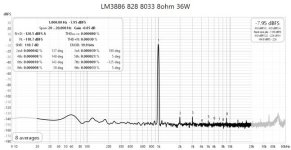
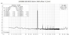
THD+N at 36W into 8Ω
(OPA828 as buffer, OP8033 as EC op-amp)
The THD+N of the DC-coupled amplifier is 0.00037%, which is nearly the same as the capacitor-coupled version with C7 (0.00038%).
Distortion still isthe even harmonics dominant component.
(OPA828 as buffer, OP8033 as EC op-amp)
The THD+N of the DC-coupled amplifier is 0.00037%, which is nearly the same as the capacitor-coupled version with C7 (0.00038%).
Distortion still isthe even harmonics dominant component.
Attachments
Bypassing a coupling capacitor shifted the distortion from being dominated by odd-order harmonics to even-order harmonics — completely unexpected.
The same audio source, the same ADC, the same signal line, and the exact same position... nothing changed, not even the environment.
I can't figure it out!
The same audio source, the same ADC, the same signal line, and the exact same position... nothing changed, not even the environment.
I can't figure it out!
Fundamental question ...... completely unexpected ... I can't figure it out!
How many cycles of the sinusoidal output are you analysing in the FFT and what is your sampling frequency ?
In order to get a proper FFT result, it is absolutely necessary to have an integral number of cycles. It may also help if the sampling frequency is an integral multiple of the test frequency, so that the above condition is easily satisfied.
With ~1k total load, the time constant is 100ms (1.6Hz). For lowest distortion you may want to go lower 10 times.Bypassing a coupling capacitor shifted the distortion from being dominated by odd-order harmonics to even-order harmonics — completely unexpected.
The same audio source, the same ADC, the same signal line, and the exact same position... nothing changed, not even the environment.
I can't figure it out!
As for AC coupling, only the master OpAmp needs it, so you could try that, increasing load to 2k, should shift the harmonic profile a bit.
Personally I'd replace the 1655 buffer with a 1/2 2156 (basically the same OpAmp, but with rail-2-rail and more robust input, and much lower offset) and place the DC-blocker in its input where a few uF of film capacitor will do. And always to a reference distortion measurement at the buffer output
I have no idea how many full sin-waves were meassured or only 1/4, 1/8 waves were taken .
I thought the software will take care of when to start, when to stop, how many times, how many waves, how to calculate etc.
Your fundamental question I am not able to anwser.
I thought the software will take care of when to start, when to stop, how many times, how many waves, how to calculate etc.
Your fundamental question I am not able to anwser.
So how do you plan on proving that your amplifier is worth it if you're unable to explain your measurement setup ?I have no idea ...
I thought the software will take care ...
for newvirus2008I just use REW. My setup is clearly shown.
I don't have the knowledge about How these instruments work, how the mathmatical principle involved in the measurement. How many 1000 waves, 100 waves, 1 wave, half wave, 1/4, 1/8, 1/16 wave I was measuring.
I use the software, hardware and setups other members use.
Can you teach me how to setup a test to measure a certain an integral number of cycles of waves using REW, a sound card and a signal source?
For instance, I want to measure only 1000 cycle 1khz waves, how should I do it in REW, with sound card?
Last edited:
Not sure, but I think there's a scope in REW where the time domain waveform could be seen and possibly exported to a *.csv file. You may then truncate the data at any number of cycles you want, using Excel etc. before doing the FFT. Alternatively, you could simply record the audio from the amplifier using software like Audacity and save any number of cycles to a separate *.wav file.
The minimum length for valid FFT is one cycle which, for 1kHz, is exactly 48 samples at a 48kHz sample rate. However, at 44.1 kHz, you'd need to do 10 cycles (10ms) to get a whole number i.e. 441 samples.
1000 cycles is a good number but it is enough if you get 1 complete cycle (or slightly more) at the highest sample rate supported by your soundcard. It is then fairly straightforward to replicate the same waveform any number of times necessary to increase the FFT resolution.
Last edited:
I think what he see is a macroscopic change, when shorting out the cap, in both configurations. The THD (as in Not THD+N) is jumping 20dB.. The second harm the most.
that means assymmetry somewhere.
A stupid question, but what is the offset in the audio source? If you have a non-negligible amount of offset at the input, in the DC coupling case it could be amplified, and introducing an imbalance all along..🤔
But be aware that the dac should be measured while actively spitting out digital zero, or very small level signal.. many dacs mute when not active.

- Home
- Amplifiers
- Chip Amps
- A New EC-Composite LM3886 Amp