Ideally, yes. In the real world performance of DUT and measuement rig can be on quite similar and very low levels, and then all you can do is to double- and triple-check with slightly changed parameters to see if a suspisciously low looking harmonic is real and not just a lucky cancelling.This is why as a rule-of-thumb the measurement equipment must be an order of magnitude better than the DUT, otherwise you can't separate the measurement of the DUT from that of the measurement equipment.
Think twice before you say that and don't forget that the even and odd harmonics represent different types of non-linearity of the transfer function, and not any linearity can be brought to linearity just applying simple phase inversion and summing.Not correct. When you have odd harmonics from, say, a symmetic expanding transfer function then a symmetric but inversly compressing transfer function can cancel it. This no different than with even order harmonics.
A simple example from the real world. If you're right then a very well balanced bridge amp would have infinitely low THD. But unfortunately it is not so. In this case the even harmonics can be significantly reduced, but not odd harmonics. If you have experience in THD measurements most probably you've seen that.
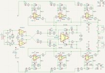

Any suggestions are welcome
This will be my last try with LM3886.
Shortly PCB for the circuit will be designed.
This will be my last try with LM3886.
Shortly PCB for the circuit will be designed.
Last edited:


You'll want to rotate the inductors so they don't couple.
That layout sure looks familiar. Gee. I wonder what inspired that. 😉
Tom
That layout sure looks familiar. Gee. I wonder what inspired that. 😉
Tom
4 layersis this 2 layers or 4?
It might be possible to connect the dots with a 2-layer layout. But keep in mind that you're trying to tame 21 A of output current while keeping any error currents well below 1 nA. That's likely impossible with a 2-layer layout. If you want performance you have to throw some copper at it.is this 2 layers or 4?
Tom
I'm interested in this project. I can help with layout. I'm most interested in the smaller amplifiers. You've done great so far. I have some layout ideas. I'm also in Toronto so exchanging hardware would be easy-ish.
My take is SMD if you want to have the PCBA produced somewhere. TH if you are going to hand-solder them. With TH you can fit slightly larger caps in the same board-area as an SMD cap as well.SMD capacitors PCB and Through-hole capacitors PCB. Not sure which one to make yet.
I also did a version with mixed components. All Aluminum Electrolytic Capacitors are through hole.

For hand soldering, the smallest SMD components are 1206. All pads are designed for hand soldering, too.
Another revision. 3 terminal linear regulators replace the cap multiplier. A power connector is added for some other uses, like speaker protection etc.

Not sure if you need any more miniaturisation, but 0805 / 0603 may also be hand soldered without consequence.For hand soldering, the smallest SMD components are 1206. All pads are designed for hand soldering, too.
- Home
- Amplifiers
- Chip Amps
- A New EC-Composite LM3886 Amp