- Yes, it is bad both for sound wires and for power too, for various reasons (a large and unstable contact resistance etc). I use either screw connectors (DG301 etc) or wire-board-type NX25/NX2500 (NXW-03 etc)More dramatic developments: There is most certainly an issue with connection quality, most probably grounding. I am using 3.5mm TRS jacks and the corresponding sockets to transfer dual DC power (which is a bad, bad and dangerous thing to do kids, and don't try this at home).
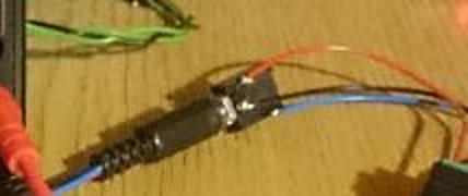
By rotating the jack inside the socket, noise levels can change dramatically. So this is a very serious aspect to take into consideration and all further experimentation will be done with as little jacks/sockets as possible, in other words using soldering and screw tightening over leads only.
Last edited:
Sorry to be slow getting back to you.
There aren't really any wrong values until ..
- the voltage drop becomes more than you want to tolerate
- the regulator, switching or otherwise, has start-up problems from too much capacitance
You could try about anything you have lying around and it would give a useful/or instructive change. Maybe 0,1 uF, X7R or other ceramic with decent high frequency performance for C1 and C2. Then 2,2 to 10 uF electrolytic for C3 and C4. For R1 and R2 you could try 1,5 ohms; about 1 ohm for R3 and R4. That would give a little under 100 mV drop @37,4 mA and should give a tidy bit of high frequency attenuation.
If it isn't enough, it might be worth tracking down a couple of AM-band or low-shortwave band ferrite beads for one leg each of R1 and R2. That'll add HF attenuation without further voltage loss.
I'll try to check back earlier tomorrow -- you're already working a lot harder than I am.😉
Cheers
Last edited:
Sorry to be slow getting back to you.
You could try about anything you have lying around and it would give a useful/or instructive change. Maybe 0,1 uF, X7R or other ceramic with decent high frequency performance for C1 and C2. Then 2,2 to 10 uF electrolytic for C3 and C4. For R1 and R2 you could try 1,5 ohms; about 1 ohm for R3 and R4. That would give a little under 100 mV drop @37,4 mA and should give a tidy bit of high frequency attenuation.
Don't you worry the slightest about it. My turnaround times can be as long as 2+ months. 🙂
I 've managed to easily source quite a few capacitors for the task. However, I can not find enough regular through hole resistors given the high tech times we live in. So I guess I can not postpone purchasing my first resistor assortment kit any longer. I 've found an E12 1 Ohm to 10 MOhm 85 values kit for a fair price.
- Yes, it is bad both for sound wires and for power too, for various reasons (a large and unstable contact resistance etc). I use either screw connectors (DG301 etc) or wire-board-type NX25/NX2500 (NXW-03 etc)
Not to mention the huge risk for shorting if you insert or accidentally pull while power is on. The tip will short the socket's tip and ring, definitely not a good thing. I 've had this happen momentarily with my SMPS, it escaped getting fried with a brief buzz and a slight smell. I have to admit it smelled good to me though. 🙂
A further note along these lines, do you guys/gals recognize this kind of 3-pin socket? I am interested in buying some of these sockets and also hopefully the corresponding connectors. This is the back of a small mixing console btw, it has an external dual AC power supply. Please let me know if you have used it or know the type!
Attachments
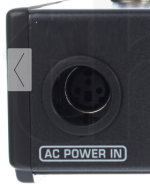
To kind of answer my own false alarm question, I think it's safe to say that the AC POWER IN displayed is a 3 pin mini DIN socket.
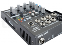
The socket I really meant to ask about is show in the following picture, again it's a small mixer with an external power adapter. This is the best angle I could find of the 3-pin socket. I included the full device for size reference. If anyone recognizes this I 'd be grateful if they let me know which type it is. I find both the 3-pin mini DIN and this unknown one very appealing for dual voltage power supply.

The socket I really meant to ask about is show in the following picture, again it's a small mixer with an external power adapter. This is the best angle I could find of the 3-pin socket. I included the full device for size reference. If anyone recognizes this I 'd be grateful if they let me know which type it is. I find both the 3-pin mini DIN and this unknown one very appealing for dual voltage power supply.
Attachments
Sorry -- it looks familiar, but I'm drawing a complete blank as to where or when it crossed my path.
Looks like a smart design for a power connector, though -- threaded collar for secure attachment.
Cheers
Looks like a smart design for a power connector, though -- threaded collar for secure attachment.
Cheers