Unfortunately this is normal behavior for a mains transformer.
They are wound such that the specified secondary voltage is present under nominal load, in your case 2x 7.5 VA. That is the norm.
Unloaded voltage is higher.
Unfortunately the difference between nominal and idle is bigger the smaller the trafo because thinner wire has higher resistance, hence larger voltage drop when loaded.
And yours is rather small...
Unfortunately this is normal behavior for a mains transformer.
They are wound such that the specified secondary voltage is present under nominal load, in your case 2x 7.5 VA. That is the norm.
Unloaded voltage is higher.
Unfortunately the difference between nominal and idle is bigger the smaller the trafo because thinner wire has higher resistance, hence larger voltage drop when loaded.
And yours is rather small...
As my earlier post shows, I was completely oblivious to these facts. But I also now fully understood the points in your post, so thank you.
Before reading your post I had found the courage (from the spec sheet) to connect the transformer to my preamp (preamp spec: max dual 15VAC). I expected to see 15VAC (after all the transformer is "under load"). I didn't get what I expected:
So, from 19.425VAC average, voltage drops to 19.140VAC average. A very slight drop and very far from 15VAC. A reminder from an earlier post in this thread:
Using the dual AC output, I ended up setting the regulator to 20.63VDC for the SPS input. In contrast, I needed about 23VDC when using the DC output. AC used more power, the regulator reports a power draw of 5.29W vs just 2.46W when using the DC output.
These power indications came from the voltage regulator I was using. I am assuming that the preamp draws only something like 3-4VA, therefore the distance from 15VAC.
Another interesting measurement I made was DC voltage on the board after the LM317/LM337 regulators, with the 19.140VAC input:
Another reminder from this thread, earlier:
Hi yannikab,
I'd like to go a step beyond kevinkr's excellent recommendation and encourage you to skip the AC input plan altogether! It's very likely a business/marketing decision that saves them a percentage of blown-up boards being returned. (Yes, I'm cynical ..😉 sorry) You already have back-to-back switching regulators (SMPS's) that are giving exactly what your boards REALLY want: Clean +/- DC at about 15V!
So if Rick means post LM317/LM337 regulation, I have accidentally hit the bullseye. I am a bit concerned however, because like I mentioned earlier, the preamp spec is dual 12VAC-15VAC max, and I am giving it 19VAC.
Do you guys/gals think the device is safe being fed by this transformer?
Also, there's this term mentioned earlier, voltage "rails". I suspect it's the points right after the regulators, currently at +-15VDC. Can someone briefly elaborate on the term though? Thanks. 🙂
Attachments


Last edited:
The regulators should be able to handle what is about +-25VDC after rectification. Make sure they have adequate heatsinks and any capacitors on the input DC rails (before the regulators) are rated at least 25v (preferably 35v).
19 VAC means very light load for that transformer (they are designed to be 80-100% loaded and hot by economical reasons).
That gives about 27 VDC after the rectifier and capacitive filter.
Capacitors (at LM317 input) must be >=35 V rated, LM317/337 can withstand it ok, but you definitely should check its heathink.
You can put some powerful resistors after the transformer to drop a portion of voltage if you want, but if there isn't very hot parts then there is no need. I think it's just fine.
I mean there isn't anything strange in +-15 V after regulators, electrical mode is ok, you just have to take care about temperature mode too.
Last edited:
Thanks for the responses guys.
The post bridge voltage prediction was quite accurate. It is in fact +-24.6VDC. The capacitors are rated at 25V.
I am glad to hear that +-15VDC post regulation is fine. Like I mentioned, regulator input is +-24.6VDC and the board has 25V stabilizing capacitors. The regulators do feel hot but not much hotter than what was my previous setup (+-16.4VDC input that ultimately translated to +-14VDC post regulation). I 'm assuming they will be just fine.
Your recommendation about using resistors to lower secondary voltage is interesting. It was my initial thought when I measured the transformer without load and saw a much higher voltage than what I expected. I looked around a bit and for the most part I saw suggestions for removing wire turns from the secondary coil, so I assumed a resistor solution is not appropriate here. Just curious, how would one go about lowering the voltage of the secondary coils without opening the (sealed) transformer? My first thought would be with something like a voltage divider, just like something we would use for a volume control, only with a bigger resistor that can handle the power.
The regulators should be able to handle what is about +-25VDC after rectification. Make sure they have adequate heatsinks and any capacitors on the input DC rails (before the regulators) are rated at least 25v (preferably 35v).
The post bridge voltage prediction was quite accurate. It is in fact +-24.6VDC. The capacitors are rated at 25V.
19 VAC means very light load for that transformer (they are designed to be 80-100% loaded and hot by economical reasons).
That gives about 27 VDC after the rectifier and capacitive filter.
Capacitors (at LM317 input) must be >=35 V rated, LM317/337 can withstand it ok, but you definitely should check its heathink.
You can put some powerful resistors after the transformer to drop a portion of voltage if you want, but if there isn't very hot parts then there is no need. I think it's just fine.
I mean there isn't anything strange in +-15 V after regulators, electrical mode is ok, you just have to take care about temperature mode too.
I am glad to hear that +-15VDC post regulation is fine. Like I mentioned, regulator input is +-24.6VDC and the board has 25V stabilizing capacitors. The regulators do feel hot but not much hotter than what was my previous setup (+-16.4VDC input that ultimately translated to +-14VDC post regulation). I 'm assuming they will be just fine.
Your recommendation about using resistors to lower secondary voltage is interesting. It was my initial thought when I measured the transformer without load and saw a much higher voltage than what I expected. I looked around a bit and for the most part I saw suggestions for removing wire turns from the secondary coil, so I assumed a resistor solution is not appropriate here. Just curious, how would one go about lowering the voltage of the secondary coils without opening the (sealed) transformer? My first thought would be with something like a voltage divider, just like something we would use for a volume control, only with a bigger resistor that can handle the power.
Last edited:
Just curious, how would one go about lowering the voltage of the secondary coils without opening the (sealed) transformer?
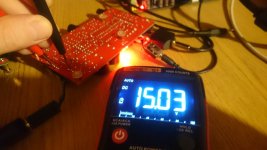
To kind of answer my own question and measure how things would work out if I added an additional device in parallel (L-R crossover), I just did it. Some numbers:
Code:
preamp alone
------------
input:
+-19.08VAC
capacitors:
+-24.56VDC
post-regulation:
+-15.03VDC

preamp and L-R x-over
---------------------
input:
+-18.34VAC
capacitors:
+-22.75VDC
post-regulation:
+-15.03VDC
I was totally NOT expecting the post-regulation voltage to stay the same, as I was used to seeing it go up and down according to the dual DC voltage I fed the preamp (I had left it at +-14VDC, best my SMPS could do without frying). Then I had this ->
Profound Epiphany: Regulators are there to provide a stable, specific voltage, provided you offer them enough power.
🙂
It is clear that the good people at the factory have set the trim pots near the regulators to +-15VDC. That's what the board wants and that's what I 'll have to provide should I want to somehow bypass the rectification or even regulation stages.
This is very cool stuff for a total newbie. I realize I am most probably lowering the quality of content on this fine forum, since my questions involve basic, barely touching the more specific subject of audio electronics. Not sure what your thoughts are about this.
As a final note (to try to touch the audio aspect of things, when using the transformer the preamp produces a very audible hum, even with the volume turned all the way down. Oddly enough it is louder on the left channel. The device used to do the same thing when I powered it with the hf AC output of my SMPS. I attribute this to well, the AC power. Of course there is a second component of noise when I turn the volume up, hiss and what clearly sounds like background EMF interference from various devices I have around, wall power etc. I will most certainly pursue powering the device with clean DC power instead.
Last edited:
Removing wire turns works only for un-sealed tranformers, of cause.
You don't need to drop voltage in your case. But if you'll have such a need, you have to know load current. Then use Ohms Law to calc additional series resistance afer the trans. But there is some nuance: because filter capacitor current is pulsating, so you have to use some coefficient which s about 3.
I mean, for example: you need to drop 3 V and load current is 0.1 A. So series resistor value have to be about 10 Ohm (but not 3/0.1 = 30 Ohm) because of that charging current pulsations.
It's actually a notch easier than the volume control example -- but that's the idea, and just as you thought -- a bigger (higher wattage rated) resistor.
It may seem wasteful 'these days', but in a bygone era when reliability/serviceability was considered more important than a few wasted milliwatts, it was standard practice in lots of consumer gear from Japan to include a series resistor to share the power dissipation. The usual location would be between the bridge/first filter caps and the regulators. But that won't remedy the issue of the marginal voltage rating of that first filter cap -- those should probably be replaced with 35V units. While they may very well last for years operating at 24.6V, good practice requires a bit of 'headroom' to allow for the inevitable line fluctuations.
If you really want to and are willing to cut foil paths, you could put an 82 or 100 ohm, 1/2W resistor in each regulator IC's supply lead. That point in the circuit will then also need a small capacitor for stability -- IIRC 0.1uF to 1uF.
The regulators will run somewhat cooler with the resistors sharing the burden, but as long as the current draw remains ~40mA (which it will -- quiescent at least), the minimum power dissipation will remain ~95mW each, due to the regulators' minimum dropout voltage. So you have choices:
**(sorry this isn't very pretty -- someday I'll figure out how to import a table)**
- no mods , , , , , , , , , , , , , ~385mW , , , , consider a small heatsink
- 82R resistor - ~130mW, , , ,~255mW, , , , 23 to 32 F degree rise
- 120R resistor - 190mW , , , , 190mW , , , , the resistor will seem warmer
- 180R resistor ~290mW , , , ,~95mW , , , , not recommended
The problem with letting the resistor dissipate all the power is that it leaves no headroom -- opamp current requirements usually vary with signal and output loading.
The arithmetic is pretty straight-forward and I'd encourage you to give it a try. When you figure out why TI's junction-to-ambient thermal resistance numbers for the LM317 are 1/2 to 1/3 of those for On Semi's and ST Micro's parts, please explain it for me. I've tried working through their SPRA953C ("http://www.ti.com/lit/an/spra953c/spra953c.pdf") and am just not getting it.
Cheers
P.S. Couple of tack-ons -- 'cause I started this before your post #26:
- Right On The Nail🙂 -- your 'regulator epiphany'! One tiny adjustment: All regulators have a 'drop-out voltage' below which regulation fails, even when there can be enough 'power'.
- Don't worry a lick about your contributions here -- your doing great! Your issues are just as 'audio' as the other stuff we fill these threads with. Glad to have you.
- Concerning the preamp hum -- I don't remember (and I'll probably loose this if I try to go find it) what sort of power requirements the preamp has .. but there's plenty of excess capacity in those LM317,337 crossover reg's. Of course, not all hum problems are the fault of the power supply. Are these planning to go into the same case?
Ooops -- still forgot something . .
Earlier you asked about 'rails' -- don't know about other, smarter folks here, but its kind of a loose term to me. In this case the likely point is the +/-15V outputs of the LM317/337's. Once in a while, in a moment of brain fog, I might refer (probably incorrectly!😱) to the rectifier-bridge/filter-caps nodes -- but that's me. Others are wiser.
Regards
Last edited:
Global 24VDC Dogma or, to put it another way, "My Lord, I have a cunning plan."
Greetings all, I hope everyone is doing well in these somewhat crazy times. A special hello to Rick after more than two months since his last response.
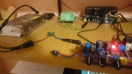
Allow me to present you with this:
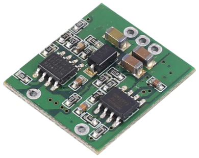
It is a DC to dual DC step down regulator. This particular board is set up for +-15VDC output and an input voltage up to 28VDC.
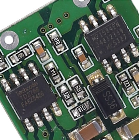
The ICs on this tiny (20mm x 23mm) board are denoted Techcode TD2786 and MPS MP1584EN:
http://www.techcodesemi.com/datasheet/TD2786.pdf
MP1584EN datasheet(1/17 Pages) MPS | 3A, 1.5MHz, 28V Step-Down Converter
I find it peculiar that they are using different step down converter ICs due to the output voltage symmetry, but I'm sure there's reasons.
So, as you might have guessed, the "cunning plan" is to use the tiny board's output to power the preamplifier board. After all, the preamp's regulators are precisely set to an output ("rail" voltage) of +-15VDC given enough juice. Doing this would change my power chain from:
LED power supply (24VDC) -> Voltage regulator -> SMPS -> preamp
to:
LED power supply (24VDC) -> tiny board -> preamp
So, it's pretty appealing.
As you might have guessed I took the liberty of connecting the tiny board's outputs directly to the preamp +-15VDC "rails" completely bypassing the rectification bridge, capacitors, and LM317/LM337 regulators. The question is, will it work?
The short answer is, urm, no. The board was operational, could reproduce sound, but the big problem was: noise. The type of noise I would describe as old analog TV or FM radio static. Oddly enough, as I managed to fry one of the two boards I got by touching it as it was operational, the second board produced a slightly different noise, but still pretty loud. So with this setup I had precisely +-15VDC on the pre's "rails" but very poor function.
Then it dawned on me, perhaps feeding the LM317/LM337 inputs with the tiny board's output would improve things. I tried it, and the noise went away for the most part - but - on the right channel only. A small note here, when I feed the board "normally" with +-15VAC there is hum, very slight on the right channel, but much louder on the left channel. So I witnessed the same thing with using +15VDC at LM317/LM337 regulator inputs, and to be honest, this could indicate poor construction or damage from my part. For the record, regulator output ("rail" voltage) was +-13.45VDC. Some drop, but expected given how the LM components work. Acceptable voltage levels but still no fireworks. (Urm, I think that was an unsuitable expression to use in this context.)
My final move was to connect the tiny board normally, pre rectification. Short story is, I get +-12.7VDC post LM regulation, the board works, and there's zero noise. Or at least, no more noise than when I powered it using other means. So it works and I should be a happy camper.
But still, something bugs me. Could I somehow have my available +-15VDC work? The preamp board is polite enough to work (normally?) at +-12.7VDC but what would I do if it didn't and my only power source was this nice +-15VDC step down regulator? In short, I am wondering if I could somehow eliminate the noise that shows up when connecting the tiny board outputs before or (even better) after the LM regulators. If you guessed I am generally thinking about various capacitors, you guessed right.
So, any ideas? And, for curiosity's sake, what's the cause of this static like noise? I really didn't expect that but silent operation instead.
I hope this was not too verbose, and thanks for reading till the end.
Yanni
Greetings all, I hope everyone is doing well in these somewhat crazy times. A special hello to Rick after more than two months since his last response.
Allow me to present you with this:
It is a DC to dual DC step down regulator. This particular board is set up for +-15VDC output and an input voltage up to 28VDC.
The ICs on this tiny (20mm x 23mm) board are denoted Techcode TD2786 and MPS MP1584EN:
http://www.techcodesemi.com/datasheet/TD2786.pdf
MP1584EN datasheet(1/17 Pages) MPS | 3A, 1.5MHz, 28V Step-Down Converter
I find it peculiar that they are using different step down converter ICs due to the output voltage symmetry, but I'm sure there's reasons.
So, as you might have guessed, the "cunning plan" is to use the tiny board's output to power the preamplifier board. After all, the preamp's regulators are precisely set to an output ("rail" voltage) of +-15VDC given enough juice. Doing this would change my power chain from:
LED power supply (24VDC) -> Voltage regulator -> SMPS -> preamp
to:
LED power supply (24VDC) -> tiny board -> preamp
So, it's pretty appealing.
As you might have guessed I took the liberty of connecting the tiny board's outputs directly to the preamp +-15VDC "rails" completely bypassing the rectification bridge, capacitors, and LM317/LM337 regulators. The question is, will it work?
The short answer is, urm, no. The board was operational, could reproduce sound, but the big problem was: noise. The type of noise I would describe as old analog TV or FM radio static. Oddly enough, as I managed to fry one of the two boards I got by touching it as it was operational, the second board produced a slightly different noise, but still pretty loud. So with this setup I had precisely +-15VDC on the pre's "rails" but very poor function.
Then it dawned on me, perhaps feeding the LM317/LM337 inputs with the tiny board's output would improve things. I tried it, and the noise went away for the most part - but - on the right channel only. A small note here, when I feed the board "normally" with +-15VAC there is hum, very slight on the right channel, but much louder on the left channel. So I witnessed the same thing with using +15VDC at LM317/LM337 regulator inputs, and to be honest, this could indicate poor construction or damage from my part. For the record, regulator output ("rail" voltage) was +-13.45VDC. Some drop, but expected given how the LM components work. Acceptable voltage levels but still no fireworks. (Urm, I think that was an unsuitable expression to use in this context.)
My final move was to connect the tiny board normally, pre rectification. Short story is, I get +-12.7VDC post LM regulation, the board works, and there's zero noise. Or at least, no more noise than when I powered it using other means. So it works and I should be a happy camper.
But still, something bugs me. Could I somehow have my available +-15VDC work? The preamp board is polite enough to work (normally?) at +-12.7VDC but what would I do if it didn't and my only power source was this nice +-15VDC step down regulator? In short, I am wondering if I could somehow eliminate the noise that shows up when connecting the tiny board outputs before or (even better) after the LM regulators. If you guessed I am generally thinking about various capacitors, you guessed right.
So, any ideas? And, for curiosity's sake, what's the cause of this static like noise? I really didn't expect that but silent operation instead.
I hope this was not too verbose, and thanks for reading till the end.
Yanni
Attachments


Last edited:
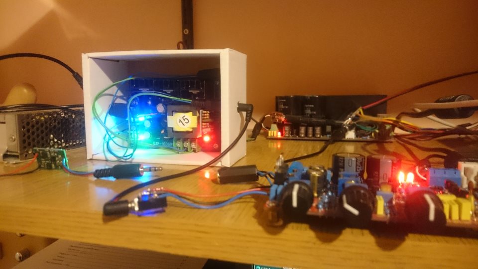
It works! Apparently, as the LEDs are not as bright as they could be, sadly. 🙂
At the bottom there's the "naughty" connection to the LM regulators. In the background, my +-15VAC transformer (unused atm) and my LM3886 power amp which I love.
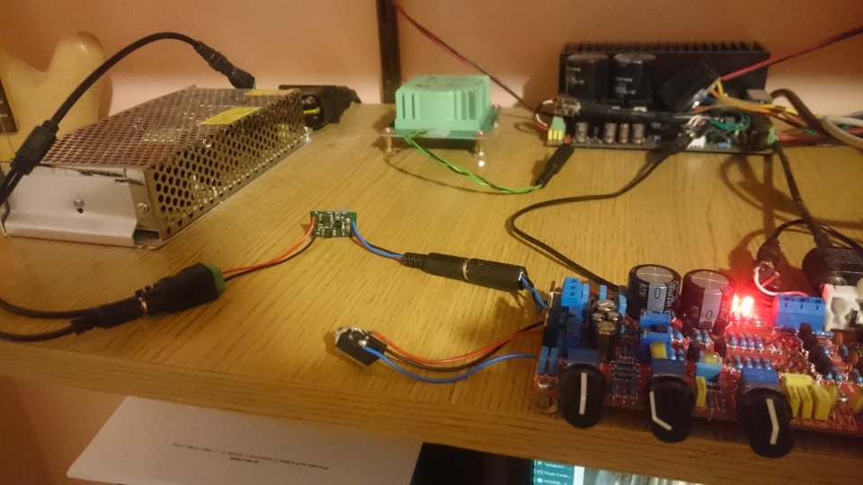
At the bottom there's the "naughty" connection to the LM regulators. In the background, my +-15VAC transformer (unused atm) and my LM3886 power amp which I love.
Attachments
Last edited:
Good to see you back at it!
That IS quite a tiny board -- and what a great find! Probably a safe bet some other folks here-abouts could put a few of those to good use, too.
Some combination of the three of these should quiet things considerably:
- a couple stages of RC filters, as close to the tiny sw-reg as possible; since the preamp's current needs are modest, the resistive losses can be as well; ferrite beads can be included if absolutely necessary
- if the +/-15V regulators are adjustable (e.g. LM317/337 -- sorry, I'm too lazy to look back to check), lower the setpoint to +/-12V and feed them AFter the bridge rectifier -- that'll give them room to regulate; otherwise they're just saturated, giving a fixed voltage drop and no noise reduction
- small, high-power-output switching regulators are *famous* for generating hard to control EMI; I don't know how coffee comes in your country, but here we have a handy, flat, can bottom of tin-plated mild steel -- folded carefully it can make an excellent little shield can
The hum is most likely a separate issue, one we can't blame that adorable little converter for.
Cheers
Thanks Rick for your response.
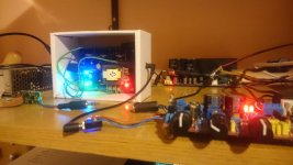
So I did the unthinkable:
The unthinkable being, connect the output of my SMPS (the device I opened this thread for) directly to the preamp's +-15V rails, post regulation. What I wanted to check is if I would have the same problem with noise that I had by connecting the tiny +-15VDC regulator board the same way.
The result was, zero noise. So I think it's clear the problem with the tiny regulator board is the way I am coupling it to the device. The bigger SMPS produces its output from hfAC so there's more than a couple of components before its dual output. Rick's recommendation about RC filtering sounds like the way to go.
I have to mention however that the plan is completely bypassing the preamp's LM317/LM337 voltage regulators. Not sure if this is a big problem if there is a proper way to directly couple the regulator board to the preamp's +-15VDC rails. In any case, the tiny regulator is not adjustable, it's set at +-15VDC and connecting it pre regulation would cause a small but unwelcome voltage drop. I 'd like to avoid it unless there's serious benefits with going through the LM regulators.
So, I guess, my question is, how do I go about building a filter that connects the tiny regulator board directly to the preamp's +-15VDC rails, hopefully eliminating noise? Provided of course this is a sound plan with no clearly better alternatives. Any advice, instructions, pointers are more than welcome as I am eager to learn more about this.
Best to all,
Yanni
Attachments
The filtering can be pretty simple, but you'll probably have to be willing to give up a few tens of millivolts. Do we know how much current the preamp board needs?
Another option would be to turn down the set-points of the LM317/337's. The preamp will surely work great with +/-12V rails -- maybe a decibel or two loss in headroom. But it isn't headroom you can use, unless you were to pad the output down 12 dB or more.
Once we know the preamp's current needs we can choose values for the filter resistors.
Glad to hear you have at least one quiet way to power it already!
Cheers
Attachments
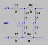
A ha! A second order filter then. Heh, I did a little bit of reading yesterday. When I'm done with this, I promise to do all the complex math concerning the first order filter, as an exercise.
Indeed, I already can power it silently. First, with the last setup shown ("big" SMPS output directly to the rails at about +-14.65VDC) and also with the tiny regulator +-15VDC going through all stages of rectification, stabilization, regulation, but at +-12.7VDC at the preamp's rails (so I don't think lowering the LM voltage settings is a better option). If I connect the tiny regulator directly to the preamp's rails there's a lot of noise, like I mentioned earlier. So I guess a regulated voltage is not equivalent to a "clean" DC voltage.
I 'll see if I can measure currents/power and come back with as much info as I can without frying my second tiny regulator (first one died when I touched it as it was working to see how hot it was!).
Here's a noise sample I just recorded. This is what the right channel sounds like with the tiny regulator directly connected to the preamp rails. Left channel is the same, at bit lower volume. The noise volume is actually pretty low. The audio clip is scarier than the real thing because I practically touched my cell phone to the right speaker. What's more impressive, the noise volume is stable. If I crank the preamp's volume to max it does not change. If I boost my source somewhat, no change. Warning: ugly sounds included.
Attachments
And sooo... some measurements. 🙂
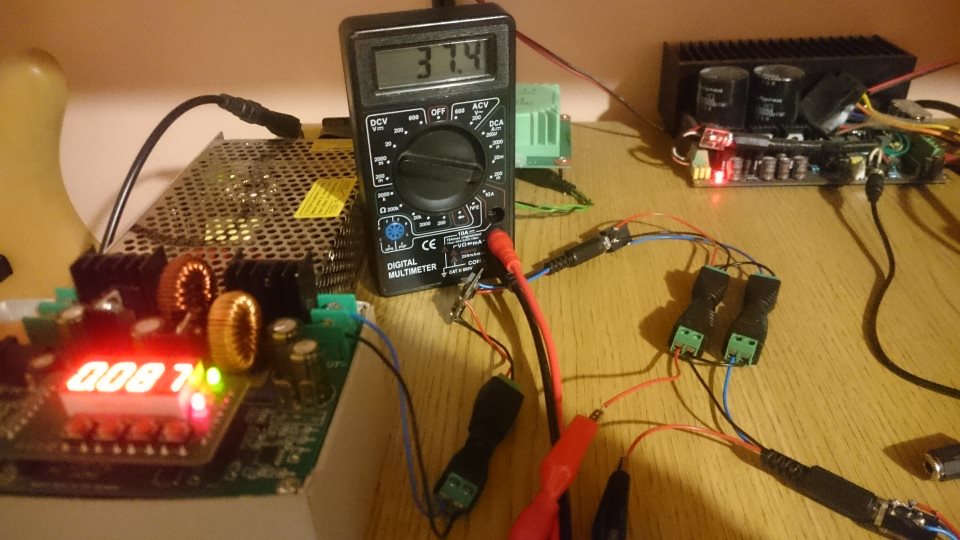
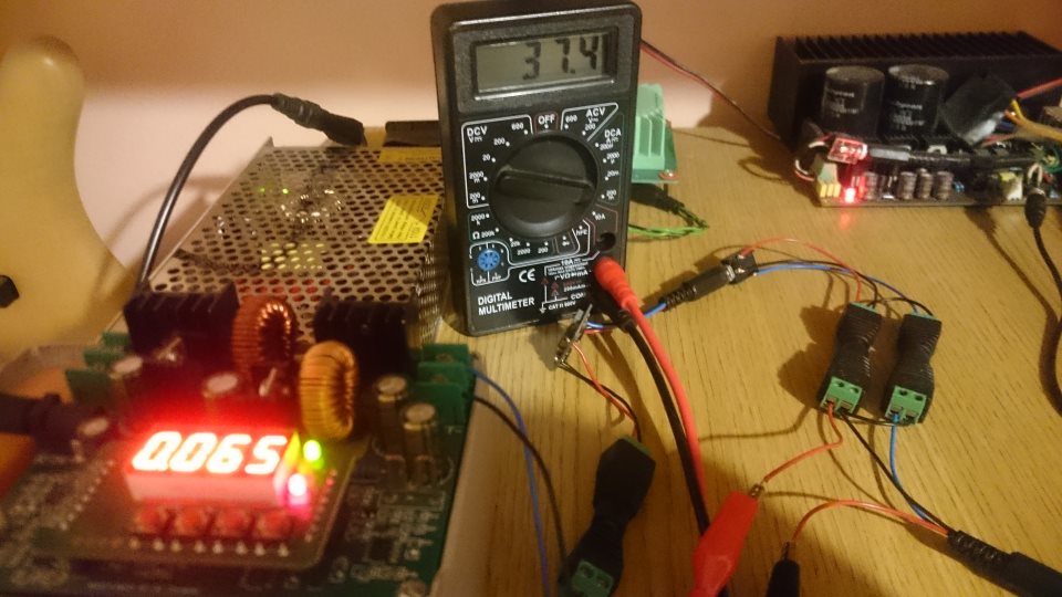
When fed 24V, the regulator module (right in front of the multimeter) draws 65mA to maintain its output voltage of +-15VDC. Just for fun I dropped input voltage to 18V, and it drew 87mA to do the same job. So in both cases it consumed about 1.560W of power. Flexibility is so very nice. 🙂 The important figure I was after, rail current, was 37.5mA in both cases. Assuming the other rail draws the same current, Power consumed by the preamp was 15.02 x 2 x 37.5, about 1.125W.
PS. Amazingly, I just noticed that noise levels depend on regulator module input voltage. When well over 20VDC, say 24VDC, there is definitely noise but not too severe. As voltage drops below 20VDC noise gradually increases until the regulator collapses (can't maintain its output) at about 16VDC input.
Attachments

Last edited:
More dramatic developments: There is most certainly an issue with connection quality, most probably grounding. I am using 3.5mm TRS jacks and the corresponding sockets to transfer dual DC power (which is a bad, bad and dangerous thing to do kids, and don't try this at home).
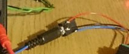
By rotating the jack inside the socket, noise levels can change dramatically. So this is a very serious aspect to take into consideration and all further experimentation will be done with as little jacks/sockets as possible, in other words using soldering and screw tightening over leads only.
Unfortunately, at their best, the noise levels are still unacceptable. So I would like to explore the RC filter option and also check what Rick mentioned earlier about this kind of component's notorious reputation for producing EMI (although the IC manufacturers claim the opposite, low EMI).
I will be recording the preamp's noise throughout the whole process. It will be lots of fun for me, especially the measuring noise power part and also if I manage to reduce noise to practically inaudible at near +-15VDC. 🙂
Attachments

Looking good! And looks like you're having some fun, too -- 
I'm gonna guess you don't want to 'sacrifice' more than about 100 mV from each +/-15V supply. That limits you to 2.67 ohms total between each pair of series resistors. Depending on the capacitors (both capacitance and other qualities -- ESR, dielectric absorption, possibly others I know nothing about) and the layout, that may not give enough attenuation. While I'd never want to discourage someone from working through the math, it may fall short of the desired payoff. At series resistance values this low, a few 10's of milliohms of capacitor ESR (or such a difference between spec sheet and 'real' values), for example, can corrupt the calculations by many decibels. Then there's the problem that we don't really know very much specific about the racket we want to filter.
I guess I'm suggesting 'trial and error' as a more expedient approach. If the attenuation still isn't enough, maybe try to source a couple of ferrite beads locally and see if that helps. An amateur radio store should be able to help, if you have one nearby.
Still, this is going great!
Cheers
I somehow sensed it would require some trial and error. I imagined you would suggest values for R and C and then I would ask you for a set of alternative values to try out too. So could you do this? Using your electronics intuition, recomnend 2 sets of RC values? If anyone else would like to chime in, by all means go ahead. I'd be happy to sacrifice say, 100-200mV and why not 500mV if it turns out it's necessary. I won't be doing the math to actually figure out some good values for R and C, it's just an exercise to freshen up my memory on signals and systems theory I did in uni long ago. 🙂
Last edited:
- Home
- Amplifiers
- Power Supplies
- A most mysterious (to me) power transformer