I prefer not to go in Europe for some PCB's, too far away for me. But if you like, I'll give you the Gerber and you can have your own made.
SY, I have a question about the servo cap C21. You spec 0.68uF, but I have in stock nice Wima 1.0uF. Would that do in this location instead of the 0.68uF specified?
No problem really SY, I'll make you a set. You worked a lot on this project and you shared the design. The least I can do is to reward you with a set of PCB at my cost.
Thanks...
I appreciate that Algar-emi. For some reason I had it in my head you were in Europe! Don't know why I thought that!!
The gerbers would be great - I haven't a clue right now what to do with them, but I'm sure I can find out.
Fran
The gerbers would be great - I haven't a clue right now what to do with them, but I'm sure I can find out.
Fran

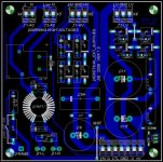
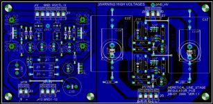
Here the first version of the external supply PCB, based on my parts list. It is single side so the HV traces are hidden as far as possible. It has 3 wire jumpers.
It includes the discrete EMI filter, ground loop breaker R & C, star ground, HV switching relay, rectifier diode snubber caps, bypass film caps and two leds, HV ON and PWR ON driving circuits.
It includes the discrete EMI filter, ground loop breaker R & C, star ground, HV switching relay, rectifier diode snubber caps, bypass film caps and two leds, HV ON and PWR ON driving circuits.
Attachments
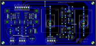
Here the preamp regulated supplies section. There is star gnd, regulator Kelvin points are directly connected to the outputs gnd to reduce supplies noise. The two HV sections are separate for Left and Right. The external supply HV relay trigger FET is also on this PCB. I choose to mount the biggest 4.7uF output caps on this PCB and the smaller 4.7uF cap directly a the tube pin on the upcoming preamp PCB. It is still a one layer PCB with a few jumpers. PCB dimensions are 4" X 8", with each section about 4"X4".
Attachments
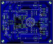
I'm trying my best. This is only a first draft. Maybe some other members can comment and I can improve the design. This PCB has some place for options. I put 3 different sizes for the film or electrolytics HV caps. I also added +/-12V suppl. filtering caps options. I had some empty space on the board anyway, so I put them just in case.
Looking good algar-emi.
I'm keen to hear how you think it sounds when you get it stuffed and fixed...
Fran
I'm keen to hear how you think it sounds when you get it stuffed and fixed...
Fran
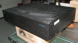
Found a nice enclosure for the preamp on my last trip. Again, recycling, it came from the garbage bin. It is a huge video input scanner for CATV surveillance system. The case is nicer than shown on my picture. It is all aluminum, with though black powder paint and very rigid, stainless steel hardware., etc . It even has rack mounting hardware. Nice thing is that the fron is all black, with no holes. I can install my own controls. Here the outside, with still some dust on it.
Attachments

- Status
- Not open for further replies.
- Home
- Amplifiers
- Tubes / Valves
- A Heretical Unity Gain Line Stage part III