@6sX7 : 1% source and gate resistors are fine and I wouldn't worry too much about matching them. That said, I do suggest a quick measurement before installation just to make sure you have the correct parts and that you don't have any duds that are way out of spec, however unlikely. Note that some care in measuring the source resistors is needed because the low resistance value means the test leads will have a significant effect on your measurements. Minimally you need to get the resistance of the test leads by shorting them and subtracting that from your measurements.
It'll be itneresting to see what your measurements are like with the new mosfets and the 1% resistors.
Have fun with your build. 🙂
It'll be itneresting to see what your measurements are like with the new mosfets and the 1% resistors.
Have fun with your build. 🙂
Dennis!,
With what happened on the last build, measured every passive component I could. So far, everything was within spec.
I gave up on matching the source resistors last night. My Fluke is only good to .1 Ohm. Did some searching, came across a suggestion of using a voltage reference and measuring the voltage drop across the resistor. I couldn't reason how this would work given that current would need to be limited and known to high accuracy and don't have a way of doing either. Figured Vishay's attestation of 1% would have to suffice and soldered them in.
JFETs are the last thing needing installing. Do that later today then find some time this week to get a channel installed and running. Will report back.

D
Deleted member 544066
So I just finished building my F4, my first of the full size FW amps, and I had used a 10k resistor for R9, and could not get enough bias, only 1.6v at full temperature. It otherwise worked perfectly, sounds great. I ordered a 5k resistor and replaced the 10k R9, but as soon as I turned the amp on, there was a buzzing/humming sound, and soon smoke, maybe from the LED? Put the 10k back in R9 and it works fine again, but still under bias. Any ideas on the issue?
Lower the bias to a minimum, change the resistor ti 5k and rebias again. And check the transistors.
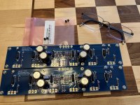
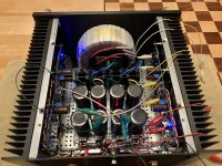
New boards are in and nothing is shorted (except the inputs). Set initial bias to 130mV on Q3 on both channels. Measured all Vgs on left channel after a few minutes
@Q10: -138mV
@Q7: -139mV
@Q6: -137mV
@Q5: 137mV
@Q4: 137mV
@Q3: 137mV
Letting it cook for an hour then will take both channels to 200 mV and remeasure.
@Q10: -138mV
@Q7: -139mV
@Q6: -137mV
@Q5: 137mV
@Q4: 137mV
@Q3: 137mV
Letting it cook for an hour then will take both channels to 200 mV and remeasure.
Attachments
Cranked Q3 to 200mV and after letting it cook for 30 minutes -
Q10: -208mV
Q7: -209mV
Q6: -208mV
Q5: 207mV
Q4: 207mV
Q3: 206mV
Happy with the results thus far so I'm done for the night. Will finish biasing tomorrow night and post the final numbers for left and right channels. Planning on cranking the bias voltage to 300mV, same as the other monsterblock.
Not sure what happened with the first build. MOSFETs were from the diyAudio store so my current assumption is I fried something during soldering or install. I didn't go thru checking Vgs before building. Set the old boards aside to troubleshoot whenever I get a workbench built up.
Today's numbers:
L ch - Q10: -299mV; Q7: -300mV; Q6: -299mV; Q5: 298mV; Q4: 297mV; Q3: 295mV
R ch - Q10: -297mv; Q7: -300mV; Q6: -299 mV; Q5: 298mV; Q4: 299mV; Q3: 294mV
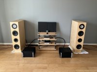
Much, much better. Have it thrown in the system with both monsterblocks operating. Balance is dead-center. No audible distortion when cranked. The Benchmark DAC3 has enough voltage swing with the balanced outputs to drive me from the room.
Will pop the tops on both amps this weekend and check numbers one last time.
L ch - Q10: -299mV; Q7: -300mV; Q6: -299mV; Q5: 298mV; Q4: 297mV; Q3: 295mV
R ch - Q10: -297mv; Q7: -300mV; Q6: -299 mV; Q5: 298mV; Q4: 299mV; Q3: 294mV
Much, much better. Have it thrown in the system with both monsterblocks operating. Balance is dead-center. No audible distortion when cranked. The Benchmark DAC3 has enough voltage swing with the balanced outputs to drive me from the room.
Will pop the tops on both amps this weekend and check numbers one last time.
Attachments
So, you are running them in "mono balanced" operation?
What is the voltage output swing from the Benchmark?
What is the voltage output swing from the Benchmark?
Still attempting to ascertain the referenceness of dBu but per benchmarks's website - 27.5 dBu. Given a factor of unknown provenance, think this is around +/-12V. It goes plenty loud. Could use a touch more gain but suits me for now. Maybe a Broskie Aikido gain stage is in the future but doesn't need much.
Each amp is being run as a mono block using the L & R balanced XLR outputs from the Benchmark.
https://benchmarkmedia.com/collecti...mark-dac3-l-digital-to-analog-audio-converter
Each amp is being run as a mono block using the L & R balanced XLR outputs from the Benchmark.
https://benchmarkmedia.com/collecti...mark-dac3-l-digital-to-analog-audio-converter
https://www.sowter.co.uk/decibels.php
I think 27.5 dBu is 17v... that's actually pretty high. My RME will do 24 dBu which is only ~12
Now, is this +/- or is it the difference between the + and -.? I think that for full output rating we need a ~30V swing.
Hmm...HOW DOES IT SOUND?
I think 27.5 dBu is 17v... that's actually pretty high. My RME will do 24 dBu which is only ~12
Now, is this +/- or is it the difference between the + and -.? I think that for full output rating we need a ~30V swing.
Hmm...HOW DOES IT SOUND?
If the recording sucks, the sound sucks. If the recording doesn't suck, dreamy. straight wire with current. Lots of detail which I'm surmising is from the drop in noise floor from operating balanced. Sounds stage is decent. Pretty sure if I gave the room some treatment love, the speakers would completely disappear.
In my setting, running a CJ PV9 single ended into a single F4, I get a middle of the hall perspective. The stage is realistically wide and deep. Pretty much I hear the sound of the preamp and it is an efficient set up, with no attenuation, just gain. I'm running the volume knob at 2 or 3 o'clock.
I've tried it with both 85 and 90 db efficient speakers... the more efficient ones really play much louder, but I find myself running the system wide open. If I turn the volume knob higher, I can start hearing the amp running out.... and there's a slight haze in the voices. The source, a DAC, is running at 2V, volume disabled.
One thing I have noticed is how low the noise is. I mean, there is no noise. So, I can play the tunes quieter but I still have dynamic range. The notes just come out from nowhere.
As you note, this is the proverbial wire.... IMHO, the end point would be an integrated built around the BA3 amp ( which I believe has the equivalent of the F4, huh? ).
It would be big though. And end up being like three boxes... so, that kind of defeats the "integrated idea"... but then, so is the XP30 Pass preamp, huh?
I'm an old guy, close to retirement and been an audiophile since my early teens, and this is as realistic a reproduction of music at home as I've ever heard.
Working on getting the BA3B and a second F4.... 🙂
ToInfiniti F4 And Beyond.
I've tried it with both 85 and 90 db efficient speakers... the more efficient ones really play much louder, but I find myself running the system wide open. If I turn the volume knob higher, I can start hearing the amp running out.... and there's a slight haze in the voices. The source, a DAC, is running at 2V, volume disabled.
One thing I have noticed is how low the noise is. I mean, there is no noise. So, I can play the tunes quieter but I still have dynamic range. The notes just come out from nowhere.
As you note, this is the proverbial wire.... IMHO, the end point would be an integrated built around the BA3 amp ( which I believe has the equivalent of the F4, huh? ).
It would be big though. And end up being like three boxes... so, that kind of defeats the "integrated idea"... but then, so is the XP30 Pass preamp, huh?
I'm an old guy, close to retirement and been an audiophile since my early teens, and this is as realistic a reproduction of music at home as I've ever heard.
Working on getting the BA3B and a second F4.... 🙂
To
~17VrmsI think 27.5 dBu is 17v...
Neither. See above. Units/nomenclature make it all clear. 🙂Now, is this +/- or is it the difference between the + and -.?

What do you mean by swing? Confirm what output power you expect into a particular load. Back-calculate the "swing" required using your own terms. No need to guess.I think that for full output rating we need a ~30V swing.
 Enjoy the tunes. Thinking about BBQ, IPAs, and Whiskey now... darn you.
My stuff is a SWAG assuming dBu is being used properly and that someone looked up the equivalent Vrms. Looks close to me.
I provided a link to a dBu to Vrms table.
For 200 watts into 4 ohms, or 100 watts into 8 ohms, we need ~28V. This is the dual mono amp balanced configuration.
For 50 watts into 4 ohms, or 25 watts in 8 ohms, we need ~14V, this is the single stereo amp single ended configuration.
I got 50 watts... I want 200. So, I need each amp to put out 28V to the speakers. RMS that is.
Just got done with the Saturday Night Fever soundtrack. Just kept listening and listening and saying "one more track before bed." Head was bopping to the disco beats. 6L6 stated it best.
No thread is good without pics. Actually, showing off my readers. So happy to be able to read JFET types, gotta show them off.

You'll know you've got them PCBs right... if you can checkmate the opponent in 3 moves 🙂
@6sX7: Now I have this image of Disco Stu. 🙂
27.5 dBu is about 18.4V RMS ( ~0.775 * 10^(27.5/20 ) ). That's about 42W into 8 ohms. In practice, there is a little voltage loss, so probably 38 or 40W max into 8 ohms.
If you want to reach that magical 100W into 8 ohms you'll need a little gain.
27.5 dBu is about 18.4V RMS ( ~0.775 * 10^(27.5/20 ) ). That's about 42W into 8 ohms. In practice, there is a little voltage loss, so probably 38 or 40W max into 8 ohms.
If you want to reach that magical 100W into 8 ohms you'll need a little gain.
- Home
- Amplifiers
- Pass Labs
- A guide to building the Pass F4 amplifier