is there a difference between the F4 2X 220uF input caps and the asymmetric M2 drive 10uF for the input from transformer and 3300uF between the gates of the mosfets ?
Please, i asked what is the minimum power supply voltage for F4. 🙂
Anybody who whant to answer? 😕
Anybody who whant to answer? 😕
The circuit is a little sensitive in that regard.
You need at least 4.5V per rail for bias requirements after an IR drop Jfet Id x 1k
You can't go too low without modifying the circuit.
Maybe 18V with the right shunt references and jfets.
You need at least 4.5V per rail for bias requirements after an IR drop Jfet Id x 1k
You can't go too low without modifying the circuit.
Maybe 18V with the right shunt references and jfets.
Thimios - I would not make F4 with rails below 24v. Build it as designed, the amplifier is incredible.
which is better?
Hi friends!
I'm not sure which way to take:
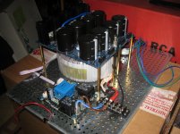
Toroid mounted vertically at the front, rectifier/CRC behind it on the floor
or
Toroid mounted on the floor, rectifier/CRC on top of it
?
Not sure about the radiation of the toroidy 18V 500VA. Assuming it is not a problem because it'd be a problem both ways.
I somehow see it like:
Tranny mounted vertically = better accessibility
Tranny underneath PSU = better weight-balance of the beast. CRC would be closer (above) the transformer...
thermally I don't see a problem (circulation is good either way)
thanks for hints!
david
PS: All seems well up to this point, soft start kicks in on itself, next is I'll test with the PSU connected. Whoo-hoo! Still not sure about the front-plate-design (switch, logo and such.) I may call it "F-4-less amp (that took me ages to build)"
EDIT: Forgot the images!
Hi friends!
I'm not sure which way to take:
Toroid mounted vertically at the front, rectifier/CRC behind it on the floor
or
Toroid mounted on the floor, rectifier/CRC on top of it
?
Not sure about the radiation of the toroidy 18V 500VA. Assuming it is not a problem because it'd be a problem both ways.
I somehow see it like:
Tranny mounted vertically = better accessibility
Tranny underneath PSU = better weight-balance of the beast. CRC would be closer (above) the transformer...
thermally I don't see a problem (circulation is good either way)
thanks for hints!
david
PS: All seems well up to this point, soft start kicks in on itself, next is I'll test with the PSU connected. Whoo-hoo! Still not sure about the front-plate-design (switch, logo and such.) I may call it "F-4-less amp (that took me ages to build)"
EDIT: Forgot the images!
Last edited:

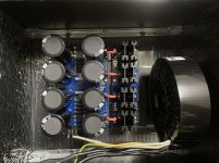
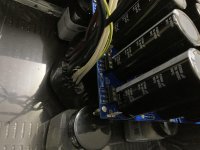
Vertical, and no issues with 99dB speakers. 4U chassis,500VA transformer, and I diyed the bracket.

CRC front mount
I mounted to the front panel. Changing orientation in comparison with transformer seemed a good idea just like speaker crossovers with multiple inductors.
https://www.diyaudio.com/forums/attachment.php?attachmentid=890757&stc=1&d=1604596772
I mounted to the front panel. Changing orientation in comparison with transformer seemed a good idea just like speaker crossovers with multiple inductors.
https://www.diyaudio.com/forums/attachment.php?attachmentid=890757&stc=1&d=1604596772
Attachments
Basic question: The cap across the leads?
I know installing a cap across Hot and Neutral is the right thing to do.
But what does it do, exactly? Prevent a spark, right?
(wondering a bit why it doesn't short hot'n neutral, but don't dare to ask this, hihi😕)
I know installing a cap across Hot and Neutral is the right thing to do.
But what does it do, exactly? Prevent a spark, right?
(wondering a bit why it doesn't short hot'n neutral, but don't dare to ask this, hihi😕)
I mounted to the front panel. Changing orientation in comparison with transformer seemed a good idea just like speaker crossovers with multiple inductors.
https://www.diyaudio.com/forums/att...guide-building-pass-f4-amplifier-img_1652-jpg
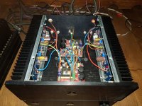
What are you doing with those little toroids next to the ps boards?
I know installing a cap across Hot and Neutral is the right thing to do.
But what does it do, exactly? Prevent a spark, right?
(wondering a bit why it doesn't short hot'n neutral, but don't dare to ask this, hihi😕)
I found this site very informative. You may too.
ABC's of Safety (Interference Suppression) Capacitors for Tube Radios
This thread also gave me a few tidbits of info. Standard discussion of "should we or shouldn't we?", but I like to read pros and cons as I learn.
X2 Line capacitors
They are choke coils replacing the R to create a CLC input power filter instead of the CRC as designed. Simply greater noise and ripple suppression on the power rails.
Ahhhh, I should have figured that out. Stupidly confused by the form factor. I've got Hammond chokes in mine as well. Not my brightest moment...
Yes, this is good! Thanks!I found this site very informative. You may too.
 !
!Hi,
I wanted to present my tiny F4 project. Maybe it will be inspiration to those with lack of space for regular F4 monster.
Case: MINI DISSIPANTE 3U - 1MNPDA03/33/300N (330mmx303mmx124mm)
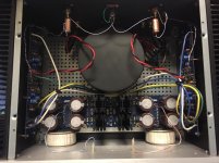
PSU: 2xSMPS300REh +/-24V. One per channel.
@ 200mV bias the heatsink temperature reaches ~54C. SMPS ~40C - so there is still capacity to go higher
It is actually crippled F4 version driven by es9038pro directly . Thank you all for all your tips.
Copule of months ago I posted such approach with SMPS and wrote that one unit failed. The issue was that I created short circuit and since that this unit was not working good. Once I repleaced the SMPS unit with the new one everything went back to normal. So this amp has been running like that for four months already with absolutely no issue ever since ...
And of course, as far as sound, the results are absolutelly fantastic!!! I got another F4 running on big toroid with massive caps so I got comparison.
Cheers,
I wanted to present my tiny F4 project. Maybe it will be inspiration to those with lack of space for regular F4 monster.
Case: MINI DISSIPANTE 3U - 1MNPDA03/33/300N (330mmx303mmx124mm)
PSU: 2xSMPS300REh +/-24V. One per channel.
@ 200mV bias the heatsink temperature reaches ~54C. SMPS ~40C - so there is still capacity to go higher
It is actually crippled F4 version driven by es9038pro directly . Thank you all for all your tips.
Copule of months ago I posted such approach with SMPS and wrote that one unit failed. The issue was that I created short circuit and since that this unit was not working good. Once I repleaced the SMPS unit with the new one everything went back to normal. So this amp has been running like that for four months already with absolutely no issue ever since ...
And of course, as far as sound, the results are absolutelly fantastic!!! I got another F4 running on big toroid with massive caps so I got comparison.
Cheers,
Attachments
Last edited:
- Home
- Amplifiers
- Pass Labs
- A guide to building the Pass F4 amplifier