Pass DIY Addict
Joined 2000
Paid Member

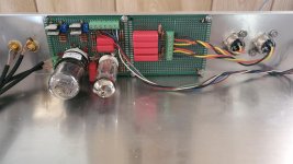
Okay, some more amp porn. Just finished another tube amp to drive the F4. This time an even simpler design: a 6CY7, which is a dual triode (driver and output) in a single envelope. I chose again to use the fabulous Type 80 rectifier and 4 ohm secondaries on the OTs.
If you guys haven’t heard the F4 driven by a flea amp, you should 😉. The distortion products of a tube amp I think go beyond descending levels of H2, H3....so on and so forth. Meaning you can’t just add H2 and H3 (as I have tried) to get exactly the same experience of having and an actual tube. Credit goes to Matt for his great and very affordable design.
https://www.cascadetubes.com/wp/wp-content/uploads/2020/09/6CY7-v2-schematic.jpg
View attachment 885857
Fugly!
Such a minimalistic design! That is like Papa's amp, but tubes 🙂 Am I correct that you will need another preamp in front of it?
No preamp necessary, in my case. I drive it with a couple of tube dacs, 3.2-3.5 vout.
This setup would provide the vast majority of builders here with enough output. If not, then I would just biamp the loudspeaker, and forget dual F4s. Just power your woofers with some serious current, and let the tube / F4 drive the upper octaves.
This setup would provide the vast majority of builders here with enough output. If not, then I would just biamp the loudspeaker, and forget dual F4s. Just power your woofers with some serious current, and let the tube / F4 drive the upper octaves.
I finally got my resistors today and, It works! It sure is nice to have 100 watts per channel. Now I can crank it up a little more.
I'm driving them with an ImPasse preamp. What a great sounding preamp! I omitted the input transformer and have absolutely no hum. I'm using an ECC99 output tube because it has a 200V heater to cathode rating. It seams like the perfect tube for this preamp. I wish there was a board available. Building it on perfboard was tedious and time consuming. I wanted to have some boards produced and maybe sell them on eBay, but I can't make head or tail out of any of the PCB software.
I'm driving them with an ImPasse preamp. What a great sounding preamp! I omitted the input transformer and have absolutely no hum. I'm using an ECC99 output tube because it has a 200V heater to cathode rating. It seams like the perfect tube for this preamp. I wish there was a board available. Building it on perfboard was tedious and time consuming. I wanted to have some boards produced and maybe sell them on eBay, but I can't make head or tail out of any of the PCB software.
If you decide to go that route and will get SY permission I will definitely get myself a set or two.
I finally got my resistors today and, It works! It sure is nice to have 100 watts per channel. Now I can crank it up a little more.
I'm driving them with an ImPasse preamp. What a great sounding preamp! I omitted the input transformer and have absolutely no hum. I'm using an ECC99 output tube because it has a 200V heater to cathode rating. It seams like the perfect tube for this preamp. I wish there was a board available. Building it on perfboard was tedious and time consuming. I wanted to have some boards produced and maybe sell them on eBay, but I can't make head or tail out of any of the PCB software.
I'm sure someone here can help with that....just ask! 😀
Member jackinnj made a PCB for Impasse. That would be the best place to start.
Also, in the thread (old and big, sorry..) there is at least one more PCB layout. Perhaps you can ask them if there are any PCB remaining or if they would share gerbers and you can order a set from JLCPCB or similar. It's remarkably easy.
ImPasse Preamplifier
Also, in the thread (old and big, sorry..) there is at least one more PCB layout. Perhaps you can ask them if there are any PCB remaining or if they would share gerbers and you can order a set from JLCPCB or similar. It's remarkably easy.
ImPasse Preamplifier
I clicked on the link at the bottom of the audioXpress article and it was dead, so I assumed it was no longer available. Oh well. I wanted to build it very compact so it would fit in a 3" high chassis. I also used quad resistors instead of power resistors which are supposed to sound better. It has separate filament connectors so I can opt for a 12SN7, and a trimpot to adjust bias. The power supply is in a separate chassis, one of those crazy Chinese tube jobs.
It seems like it would be pretty easy to make a PCB with a similar layout by someone who knows what they're doing.
It seems like it would be pretty easy to make a PCB with a similar layout by someone who knows what they're doing.
Attachments

Guys,
Could you please validate my idea.
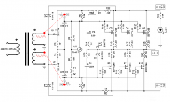
Basically I would like to get rid of 220uf coupuling caps from sigal path in F4.
I got DIY ak4493 dac with transformer output. Audio output transformer is special. It has one primary and two seconderies. This means it can output two same signals (not differential signals).
I need no preamp because I got high efficiency speakers 95db and direct ouput from dac is enough.
With all above, could I connect output signals from transformer directly before 150R gate resistors and right after 220uf cap? Please take a look a the attched picture and let me know please if it make sense. The picture represents one channel.
Could you please validate my idea.
Basically I would like to get rid of 220uf coupuling caps from sigal path in F4.
I got DIY ak4493 dac with transformer output. Audio output transformer is special. It has one primary and two seconderies. This means it can output two same signals (not differential signals).
I need no preamp because I got high efficiency speakers 95db and direct ouput from dac is enough.
With all above, could I connect output signals from transformer directly before 150R gate resistors and right after 220uf cap? Please take a look a the attched picture and let me know please if it make sense. The picture represents one channel.
Attachments
Last edited:
As shown the dc bias of the output stage will be on the transformer secondary.
Ok, so the only question is whether ~200mV DC hits transformer saturation limits?
With potentiometer P1 set to 0 ohms, the voltage across Q11 is 9.35 volts (using the equation in the TL431 datasheet)
With potentiometer P1 set to 5K ohms, the voltage across Q11 is 7.07 volts (using the equation in the TL431 datasheet)
About half of that appears across C1 and the other half appears across C2
_
With potentiometer P1 set to 5K ohms, the voltage across Q11 is 7.07 volts (using the equation in the TL431 datasheet)
About half of that appears across C1 and the other half appears across C2
_
Unless specifically designed and made to have DC in the core, for example a single-ended vacuum tube output transformer, having any DC in the transformer is a good thing to avoid.
I've not seen any small-signal transformers that are made to handle anything aside from uA of DC.
The long story made short is C1 and C2 are absolutely essential for the operation of F4.
I've not seen any small-signal transformers that are made to handle anything aside from uA of DC.
The long story made short is C1 and C2 are absolutely essential for the operation of F4.
Unless specifically designed and made to have DC in the core, for example a single-ended vacuum tube output transformer, having any DC in the transformer is a good thing to avoid.
I've not seen any small-signal transformers that are made to handle anything aside from uA of DC.
The long story made short is C1 and C2 are absolutely essential for the operation of F4.
To bad then ... 🙁 Thank you.
Too bad? Essentially everybody who has built F4 finds it to be their favorite Firstwatt amplifier. It is a diamond amongst gems. 
Put one secondary in series between the tl431 leg and the gate stoppers of the mosfets.
A la pass F6
A la pass F6
One winding for the irfp240 and one winding for the 9240 like you already drawed.
Omit the input buffer.
Your DAC has 700ohm output impedance....
I have the same dac in the dcx2496
Omit the input buffer.
Your DAC has 700ohm output impedance....
I have the same dac in the dcx2496
Guys,
Could you please validate my idea.
Basically I would like to get rid of 220uf coupuling caps from sigal path in F4.
I got DIY ak4493 dac with transformer output. Audio output transformer is special. It has one primary and two seconderies. This means it can output two same signals (not differential signals).
I need no preamp because I got high efficiency speakers 95db and direct ouput from dac is enough.
With all above, could I connect output signals from transformer directly before 150R gate resistors and right after 220uf cap? Please take a look a the attched picture and let me know please if it make sense. The picture represents one channel.
as you drew it (phases, not going in details will you burn xformer secondary or not in that way) , you practically have M2 - xformer driving source follower OS
Too bad? Essentially everybody who has built F4 finds it to be their favorite Firstwatt amplifier. It is a diamond amongst gems.
naah
F4 is for Sissies, it's well known that M2 is best FW amp

- Home
- Amplifiers
- Pass Labs
- A guide to building the Pass F4 amplifier