I would like to recommend using a valve pre-amp with the F4.
The F4 is really very transparent, so you can get the sound of tubes with the advantage of current in such a combo.
Higly recommended!
The F4 is really very transparent, so you can get the sound of tubes with the advantage of current in such a combo.
Higly recommended!
In my final design I will have integrated my Aikido in to my parallel F4.
It will be kinda chunky but atleast it will take up less desk space.
It will be kinda chunky but atleast it will take up less desk space.
Thanks everyone for all the encouragement and insight. Thanks 6L6 for the support. This is all inspiring.
Now I just need to decide between the F4 and Aleph J, or nor worry about my balanced sources and go single ended. I like the flexibility of the F4.
Most have said that the F4 is the sound of your preamp. Since I have an Aleph P and have not used it in and ideal situation, does anyone know the sonic signature of it? This will help me decide in my amp choice.
Thanks again for the encouragement.
The Aleph P does not have a bucket of gain... However most people don't need anywhere near as much power as they think, so it might be plenty with an F4.
There is no doubt in my mind that it will sound fantastic.
The Aleph J is SE or BAL in, and will go to full output with that preamp. It will also sound wonderful.
Check your PM.
There is no doubt in my mind that it will sound fantastic.
The Aleph J is SE or BAL in, and will go to full output with that preamp. It will also sound wonderful.
Check your PM.

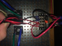
Each amp PCB gets connected to V+, V-, and ground. You already have the grounds tied together on the PCB - that's good.
Excellent, thank you. Just wanted to be sure I wasn't missing something that may be obvious to others. So that leaves the rectifier side, which I assume I wire just as shown in the F5 thread, and the chassis ground - which I know ties to the ground of the iec outlet...and from there I'm lost again 🙂.
The rectifier wiring appears good.
The safety ground (earth) needs to be attached - go from the 3rd pin on the IEC straight to the chassis.
Connect a CL-60 from PSU ground straight to the chassis.
The safety ground (earth) needs to be attached - go from the 3rd pin on the IEC straight to the chassis.
Connect a CL-60 from PSU ground straight to the chassis.
Have you seen a test of this assembly?..............Connect a CL-60 from PSU ground straight to the chassis.
Can it survive a kA event and survive long enough to Blow the mains fuse and allow time for the arc to extinguish?
But can it survive long enough for the Fault Current to blow the Mains fuse and for the arc to extinguish?
Ask Nelson.
But when you consider that a CL- is designed to normally have the mains running through it 100% during normal operation, I suspect the answer is yes.
But when you consider that a CL- is designed to normally have the mains running through it 100% during normal operation, I suspect the answer is yes.
A CL60 is designed to pass "normal" currents.
I asked a few times about the modified Bridge Rectifier version of the Disconnecting Network.
No Member came forward with evidence of "safe" to use" as suggested.
I tested it.
The size of the explosion surprised me.
Even more surprising was that I could not detect any damage or changed parameters in the Disconnecting Network components.
I now recommend the bridge rectifier Disconnecting Network.
I have never put a CL60 to such a "test"
Two reasons:
1.) I am not on a 110/120Vac Mains supply
2.) I don't have any CL60 NTCs
Maybe you should try to find "evidence" that what you and Pass are suggesting is safe on 110/120Vac fault currents.
I think a little clarification is in order for those of us who aren't EE's.one would assume that if this is the grounding scheme utilized in production FW amplifiers that it is perfectly safe for our homebrew editions. Is this not the case? Also, other than a lightning bolt ( which would be stopped by proper protective equipment long before reaching any of my components ),when and how is a kA going to make its way to ground through my amp. Please elaborate.
the Fault Current is limited by the impedance of the Source (the Mains supply) and the impedance of the house wiring.
This can be much less than an ohm.
With a 240Vac supply having a maximum voltage of 359Vpk, the Fault Current that can flow can approach a kA.
Look at your MCBs. They are rated for maximum non fault current and also rated for ability to break Fault Current. I expect to see 6kA or 10kA on UK MCBs.
Even RCCBs (RCDs) are rated for their ability to break Fault Current.
Gone out and checked, all my Merlin Gerin and Dorman Smith are rated 10000 (=10kA)
If you are going to work with Mains Powered projects, then it is your responsibility to make your self aware of the risks.
Last edited:
- Home
- Amplifiers
- Pass Labs
- A guide to building the Pass F4 amplifier