Perhaps a modification to consider??
Hi Elbert,
The loop breaker is a 'last resort' type of solution and should only be used if you have exhausted all of the usual ways to kill ground loops. I've just learned this actually, through my work with guitar amps.
As I'm currently working on a new 6 channel amp, I'll be implementing what I've learned into the ground scheme and it is my belief that I will be able to avoid loop breakers all together.
5th,
Unfortunately, many of the pictures you uploaded do not shwo, but I've tried my best to follow the text, and I think I can make quite good sense of it! 🙂
Good idea to use a camera in stead of a scanner, must admitt that never crossed my mind! 🙂
Well, I have now made some further progress in that I have implemented the fround-breaker mod on all three cards in one chassis.
The effect is that I can now connect all amp input grounds together and when shorting the inputs, I get about the same noise level on the outputs. To me, this proves that this modification has been successfull in breaking ground loops between 0V of the three cards.
So far so good.
The input RCA, connected to the X-over, is insulated from the chassis, so no loop connection there.
But I still get a bit of hum, especially on the second and third card, and inserting the mu-metal behind the transformer still has a significant effect on this.
As I should now have gotten rid of all obvious ground loops, I think my remaining problem is hum induction in to the X-over card, and perhaps some hum induction from PSU wires that are not properly twisted.
When connected to the x-over board, the third amplifier, i.e. the sub amplifier still has significantly more hum and garbage on the output..
Looking at the X-over schematics, I used some rather high ohm resistors in that part of the network due to the capacitor values I had set in the sub LP filter. These were around 100K whilst most of the other resistors were in the 1-4k range. Perhaps this makes the sub LP particularily sensitive to hum??
Hi Elbert,
The loop breaker is a 'last resort' type of solution and should only be used if you have exhausted all of the usual ways to kill ground loops.
I'm going to repeat what John has said here. As you can see from the images I've posted, there would have been ways to implement many ground breaker resistors perhaps, in solving some of my problems.
However I didn't need to do this, with a rethink about the internal grounding I was able to connect everything in my 6 channel amp without a single ground breaker resistor. The only ground breaker needed is the one required to stop a loop forming through the safety earth connection.
I find this highly unlikely, but are there any loops internal to the amplifier cards that you're using now?
As you can see from the images I've posted,
Well, actually 5th, they still aren't showing for me.
Well, actually 5th, they still aren't showing for me.
Even if you use 'middle click' in something like firefox which opens the image in a new tab? The same works in google chrome. Alternatively you can right click the link and select 'open link in new tab'.
This also works if I'm not logged into DIYaudio, so it's not a permissions things either.
Edit - Oh I see what I've done wrong, I've not provided links that have a .jpg extension, which is why the forum isn't displaying thumbnails. Would be great if I could edit the post and change that. Alternatively I could post it for a third time and get a mod to delete post 224>.<
Hurrah fixed it, if a mod could delete post 224 that would be great. I've already PM'd Cal to delete 218 🙂
Last edited:
If we're talking about a standard earth breaker resistor, such as would be implemented between the star ground and the mains earth, then it doesn't matter quite so much what the value is.
The point of the earth disconnect resistor is to control where the ground currents are choosing to flow. Say you've got two devices connected via shielded interconnects and those two devices are also connected to the mains earth via the earthing pin in the IEC connector. You've instantly created a loop.
From the first device into the second device via the interconnects, from the second device to the mains earth via it's IEC connector, then from the mains earth into the first device via it's IEC mains connector. Due to the slight difference in ground potential between the two devices a current will flow through the interconnect shield, this is where you get your induced hum from. If you place a ground breaking resistor in one device the current will no longer flow as you've 'disconnected' one device from the mains earth and in doing so, broken the loop, thus the hum stops. This is why double insulated devices are common in hifi for pre amps and CD players etc. You can't get a ground loop between devices if there is no connection to mains safety earth to begin with!
This illustrates the point of a 'breaking/lifting' resistor, it creates a path of relatively high impedance somewhere in the grounding organisation and as a result stops a current flowing in an area you don't want it to flow.
Inside a piece of equipment, you can add as many of these as you want, if necessary, to control the direction of the ground currents. You have to do this with caution however as you absolutely must not break a circuits return path to the star point. The breaker resistor is merely used to prevent unwanted ground interaction between independently functional blocks.
The one area where it is so very easy to create a loop is such as the situation you are facing with your active crossover + amplifier in a single chassis.
Naturally the amplifier has a power return, a signal return and a return from the load.
The power return is from the decoupling capacitors and has been dealt with by taking it separately back to a point so very slightly downstream of the audio signal return.
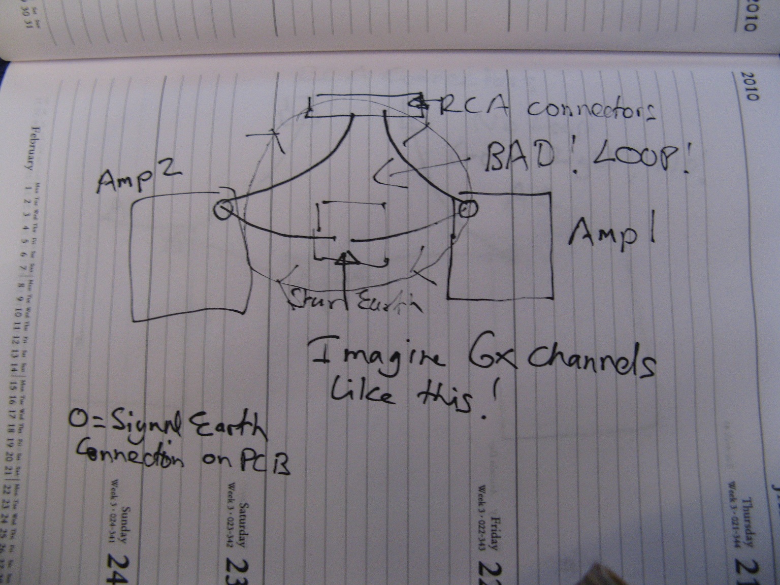
The load return goes back to the main star point as does the signal return. BUT, and here's the main but, the signal ground also connects to the input RCA connectors. If the chassis is connected to the star point you've just created a loop right there inside the amplifier BAD! This is why John and I don't have the RCA connectors electrically connected to the chassis.
In my 6 channel amp the RCA connectors are all connected together on that common aluminium plate and the signal ground from the RCA connectors goes directly to the signal ground on the amplifier PCBs. So far so good, but the amplifier signal ground (as this includes the feedback networks shunt resistor) also has to be connected to the star ground inside the case.
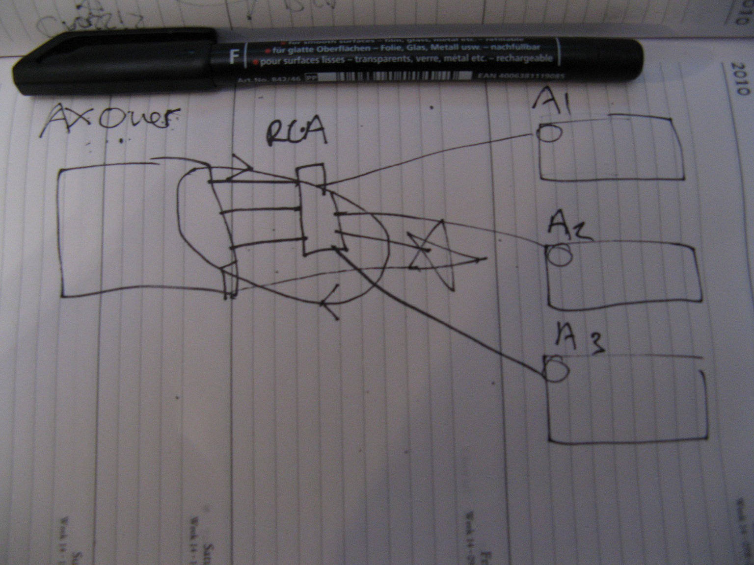
If I connect the signal ground from each amplifier channel back individually to the star point, you'd think, okay fine, job done! That's what I thought, but no! It didn't work. Why? Because connecting each amplifiers PCB signal return trace back to the star ground created a loop and not just one loop LOTS of loops. (P.S you can take pictures of a drawing with a digital camera, you don't need a scanner!)
Here's that scenario;
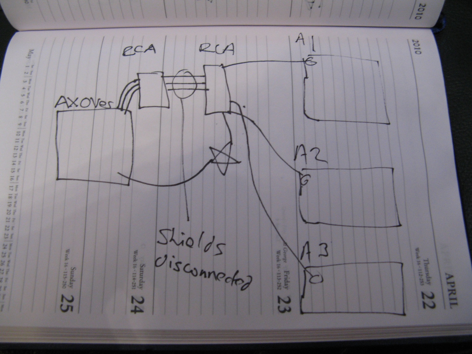
Well okay I thought, this is bad, lets separate the RCA connectors right?
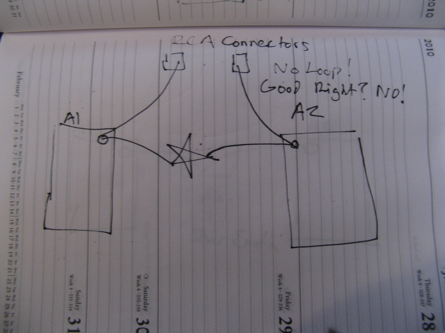
WRONG!
Okay so now what? Lets join the RCA connectors back together again, only this time...
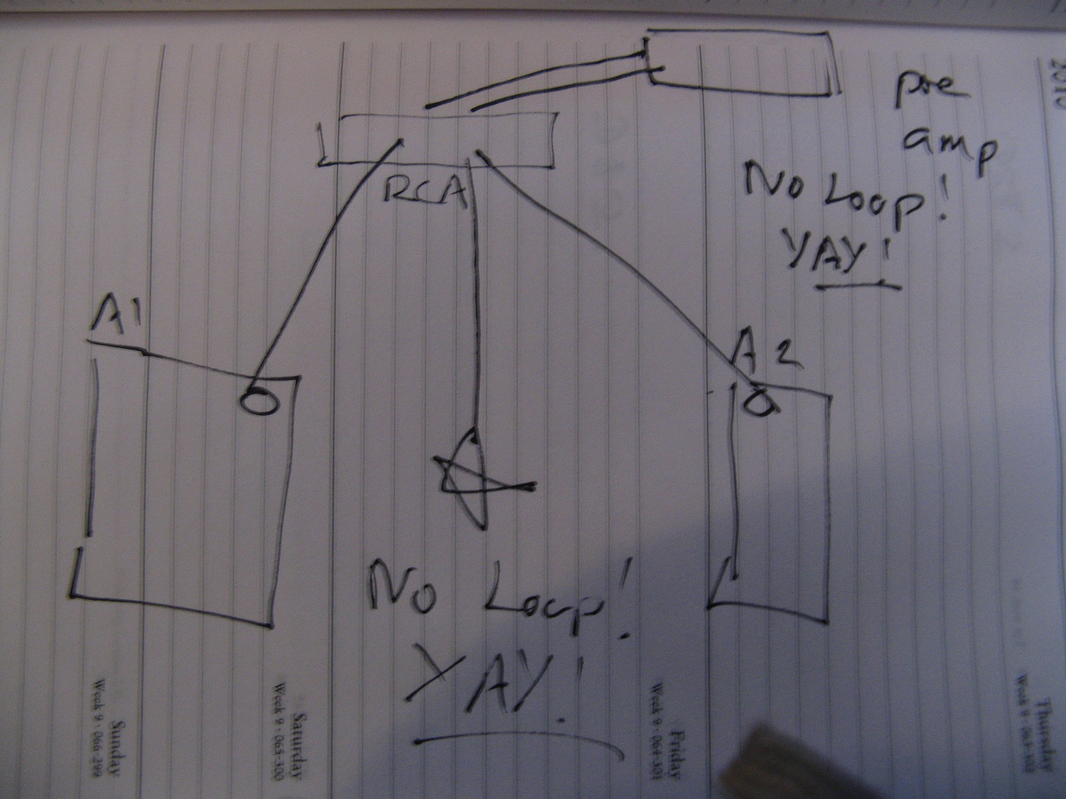
Yay finally solved it.
The only possible loop left would be like I first described and that would be when the two units are connected via the mains earth, as now we've got the units connected together via the RCAs and via the mains earth connection = loop. Sometimes this isn't a problem, sometimes it is! This is why you use the disconnect resistor and this is why the RCA connectors are mounted separate of the chassis. The chassis MUST !100% be connected to the mains earth, NO resistors, no nothing, otherwise it's unsafe.
If your RCA connectors were connected to the chassis, then placing a resistor disconnect between the star earth and the mains earth would do nothing. Why? Because the star earth will still have a direct path back to mains earth via the RCA connectors. The mains earth is connected to the chassis, the chassis is connected to the RCA connectors and the RCA connectors go back to star earth, so you're not achieving anything with your disconnect, all you did was break another internal loop.
This is why Douglas Self says (if the RCA connectors are connected to the main chassis), connect the safety earth @ the RCA connectors. The RCA connectors are connected back to the star point and the star point is connected back to the IEC safety earth pin. This way you have zero internal loops, but you cannot use a disconnect resistor as that would connect the chassis to safety earth via a resistor = bad, even if through the diodes.
If you break the RCA connectors off from the chassis, then you can have the chassis connected directly to safety earth. Naturally you still connect the star ground back to mains safety earth too at the IEC plug, but now if there's a loop created when you plug two components together you can use a breaking resistor between the star point and the IEC plug inside one of the components. Both chassis still have a direct connection with safety earth so safety is preserved.
The disconnected ground is still connected to mains safety earth via the diodes, so if a dangerous fault condition should appear internal to the electronics, the diodes will conduct and fuses somewhere should blow.
The first task you should accomplish is connecting all three amplifier channels together with zero internal loops. And zero internal loops when the amplifier RCA connectors are plugged into another device.
As Andrew has mentioned you start with one channel, then work your way up. If you're lucky the technique used to connect two channels up successfully can be repeated for as many channels as you have.
Only once you've connected up the amplifier do you start with the active crossovers.
This is where trouble can ensue though and judicious use of disconnect resistors is highly recommended.
So say you've got your amplifiers configured as I solved my issue and then you go adding in the active xover module in this way.
In this situation the active xover has it's ground connection made directly back to the star ground. You have also got the signal return from the RCA connectors from the amp connected back to the ground connection on the active xover PCB.
This creates a loop and you get hum. What does it remind you of?
That's right the ground loop occurring between two different components as described at the start of this post that is corrected by the insertion of a ground lifting resistor. Only instead of the loop being created by the safety earth, it is now being created by common star ground.
Can we safely remove the earth connection from the xover module to the star ground? Yes, IF we keep the ground connection to the xover module through the RCA connectors there at all times. Is this a good idea? NO! Why? Because if you want to disconnect the active xover from the power amps what happens to its ground return, it goes poof and then so might the active xover. Also any return current from the active that is NOT signal related will be forced to flow through the RCA shield. This is bad!
Remember this?
This created a horrendous degradation in the amplifier performance. Because of the loop, some of the return current from the load went into the loop, not a lot mind you, but some did! That was all it took and the distortion performance went from like 0.0003% to 0.02%. This is an exaggeration of your situation as the return currents for the active xover are likely to be very small. Still the only current that should be flowing from the amplifier and back into the active xover board, should be the return current for the signal sent through the RCA connector.
So what about the alternative?
The alternative is to disconnect the ground connection from the active xover board that goes into the shielded wire that connects to the RCA connector. This will break the loop and force any return current to go through the star return point and back down the wire that connects the active xover board to the star point. Is this bad? Not really. What's the down side? Of course there had to be a down side right? Yup!
Lets say you want to connect the output from one of the active xover cards to another amplifier somewhere else? Now the signal the active xover card puts out can flow down the wire to the other amplifier, but where does the return current flow? Urrg hmm? The RCA ground connection to the active xover board isn't there so er... Okay right, your other amplifier is double insulated and has no ground connection at all, so err... it CANNOT RETURN ANYWHERE! through the ether! yes! Lets break the laws of physics!
This isn't ideal either what can be done?
Here we have a second set of three RCA connectors mounted on their own piece of metal, with a return back to the active xover PCB. Now you can connect the active xover to another amplifier without any trouble.
This isn't ideal either why? Because ideally you'd like to be able to connect the power amplifier to the active xover card with a shielded internal cable. Okay, well how do we do that? This sounds vaguely familiar right? Sure does, when you've got a completely separate box that does active xover and a completely separate power amplifier.
Like..
Only the active xover resides in the same case as the power amplifiers instead. How do we do this? Easy!
Treat the active xover card and its power supply as if it were an independent unit.
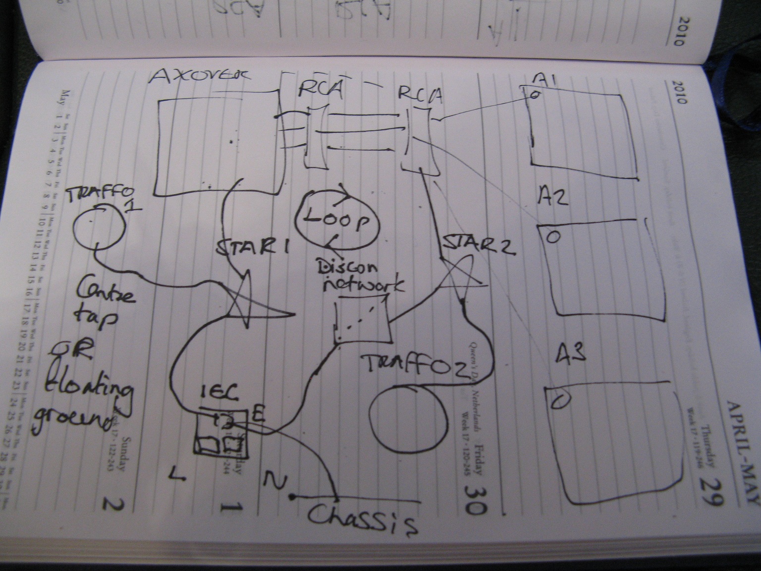
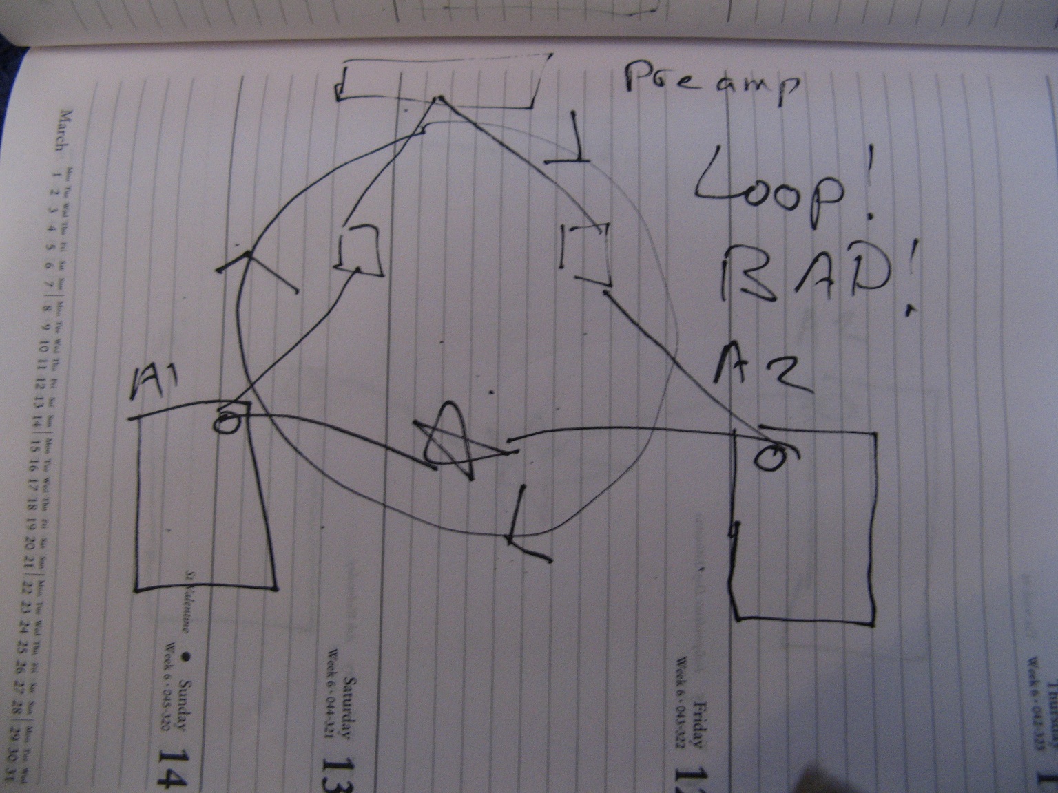
As you can see this closely resembles two individual boxes, say a preamp and a power amp. With two individual boxes and two IEC connectors back to safety earth, we have two different possible potentials for the units to be at and hence a ground loop forms, a current flows and we get hum. If both units are in the same case this isn't going to be an issue, the IEC connector is common to them both, but we still need a disconnect module otherwise the internal loop shown will form.
It should be noted that if your source (CD player etc) isn't double insulted you might need another disconnect network from Star 1 back to the safety earth pin.
I hope I haven't goofed something up with all of that and I hope it helps!
The point of the earth disconnect resistor is to control where the ground currents are choosing to flow. Say you've got two devices connected via shielded interconnects and those two devices are also connected to the mains earth via the earthing pin in the IEC connector. You've instantly created a loop.
From the first device into the second device via the interconnects, from the second device to the mains earth via it's IEC connector, then from the mains earth into the first device via it's IEC mains connector. Due to the slight difference in ground potential between the two devices a current will flow through the interconnect shield, this is where you get your induced hum from. If you place a ground breaking resistor in one device the current will no longer flow as you've 'disconnected' one device from the mains earth and in doing so, broken the loop, thus the hum stops. This is why double insulated devices are common in hifi for pre amps and CD players etc. You can't get a ground loop between devices if there is no connection to mains safety earth to begin with!
This illustrates the point of a 'breaking/lifting' resistor, it creates a path of relatively high impedance somewhere in the grounding organisation and as a result stops a current flowing in an area you don't want it to flow.
Inside a piece of equipment, you can add as many of these as you want, if necessary, to control the direction of the ground currents. You have to do this with caution however as you absolutely must not break a circuits return path to the star point. The breaker resistor is merely used to prevent unwanted ground interaction between independently functional blocks.
The one area where it is so very easy to create a loop is such as the situation you are facing with your active crossover + amplifier in a single chassis.
Naturally the amplifier has a power return, a signal return and a return from the load.
The power return is from the decoupling capacitors and has been dealt with by taking it separately back to a point so very slightly downstream of the audio signal return.
The load return goes back to the main star point as does the signal return. BUT, and here's the main but, the signal ground also connects to the input RCA connectors. If the chassis is connected to the star point you've just created a loop right there inside the amplifier BAD! This is why John and I don't have the RCA connectors electrically connected to the chassis.
In my 6 channel amp the RCA connectors are all connected together on that common aluminium plate and the signal ground from the RCA connectors goes directly to the signal ground on the amplifier PCBs. So far so good, but the amplifier signal ground (as this includes the feedback networks shunt resistor) also has to be connected to the star ground inside the case.
If I connect the signal ground from each amplifier channel back individually to the star point, you'd think, okay fine, job done! That's what I thought, but no! It didn't work. Why? Because connecting each amplifiers PCB signal return trace back to the star ground created a loop and not just one loop LOTS of loops. (P.S you can take pictures of a drawing with a digital camera, you don't need a scanner!)
Here's that scenario;
Well okay I thought, this is bad, lets separate the RCA connectors right?
WRONG!
Okay so now what? Lets join the RCA connectors back together again, only this time...
Yay finally solved it.
The only possible loop left would be like I first described and that would be when the two units are connected via the mains earth, as now we've got the units connected together via the RCAs and via the mains earth connection = loop. Sometimes this isn't a problem, sometimes it is! This is why you use the disconnect resistor and this is why the RCA connectors are mounted separate of the chassis. The chassis MUST !100% be connected to the mains earth, NO resistors, no nothing, otherwise it's unsafe.
If your RCA connectors were connected to the chassis, then placing a resistor disconnect between the star earth and the mains earth would do nothing. Why? Because the star earth will still have a direct path back to mains earth via the RCA connectors. The mains earth is connected to the chassis, the chassis is connected to the RCA connectors and the RCA connectors go back to star earth, so you're not achieving anything with your disconnect, all you did was break another internal loop.
This is why Douglas Self says (if the RCA connectors are connected to the main chassis), connect the safety earth @ the RCA connectors. The RCA connectors are connected back to the star point and the star point is connected back to the IEC safety earth pin. This way you have zero internal loops, but you cannot use a disconnect resistor as that would connect the chassis to safety earth via a resistor = bad, even if through the diodes.
If you break the RCA connectors off from the chassis, then you can have the chassis connected directly to safety earth. Naturally you still connect the star ground back to mains safety earth too at the IEC plug, but now if there's a loop created when you plug two components together you can use a breaking resistor between the star point and the IEC plug inside one of the components. Both chassis still have a direct connection with safety earth so safety is preserved.
The disconnected ground is still connected to mains safety earth via the diodes, so if a dangerous fault condition should appear internal to the electronics, the diodes will conduct and fuses somewhere should blow.
The first task you should accomplish is connecting all three amplifier channels together with zero internal loops. And zero internal loops when the amplifier RCA connectors are plugged into another device.
As Andrew has mentioned you start with one channel, then work your way up. If you're lucky the technique used to connect two channels up successfully can be repeated for as many channels as you have.
Only once you've connected up the amplifier do you start with the active crossovers.
This is where trouble can ensue though and judicious use of disconnect resistors is highly recommended.
So say you've got your amplifiers configured as I solved my issue and then you go adding in the active xover module in this way.
In this situation the active xover has it's ground connection made directly back to the star ground. You have also got the signal return from the RCA connectors from the amp connected back to the ground connection on the active xover PCB.
This creates a loop and you get hum. What does it remind you of?
That's right the ground loop occurring between two different components as described at the start of this post that is corrected by the insertion of a ground lifting resistor. Only instead of the loop being created by the safety earth, it is now being created by common star ground.
Can we safely remove the earth connection from the xover module to the star ground? Yes, IF we keep the ground connection to the xover module through the RCA connectors there at all times. Is this a good idea? NO! Why? Because if you want to disconnect the active xover from the power amps what happens to its ground return, it goes poof and then so might the active xover. Also any return current from the active that is NOT signal related will be forced to flow through the RCA shield. This is bad!
Remember this?
This created a horrendous degradation in the amplifier performance. Because of the loop, some of the return current from the load went into the loop, not a lot mind you, but some did! That was all it took and the distortion performance went from like 0.0003% to 0.02%. This is an exaggeration of your situation as the return currents for the active xover are likely to be very small. Still the only current that should be flowing from the amplifier and back into the active xover board, should be the return current for the signal sent through the RCA connector.
So what about the alternative?
The alternative is to disconnect the ground connection from the active xover board that goes into the shielded wire that connects to the RCA connector. This will break the loop and force any return current to go through the star return point and back down the wire that connects the active xover board to the star point. Is this bad? Not really. What's the down side? Of course there had to be a down side right? Yup!
Lets say you want to connect the output from one of the active xover cards to another amplifier somewhere else? Now the signal the active xover card puts out can flow down the wire to the other amplifier, but where does the return current flow? Urrg hmm? The RCA ground connection to the active xover board isn't there so er... Okay right, your other amplifier is double insulated and has no ground connection at all, so err... it CANNOT RETURN ANYWHERE! through the ether! yes! Lets break the laws of physics!
This isn't ideal either what can be done?
Here we have a second set of three RCA connectors mounted on their own piece of metal, with a return back to the active xover PCB. Now you can connect the active xover to another amplifier without any trouble.
This isn't ideal either why? Because ideally you'd like to be able to connect the power amplifier to the active xover card with a shielded internal cable. Okay, well how do we do that? This sounds vaguely familiar right? Sure does, when you've got a completely separate box that does active xover and a completely separate power amplifier.
Like..
Only the active xover resides in the same case as the power amplifiers instead. How do we do this? Easy!
Treat the active xover card and its power supply as if it were an independent unit.
As you can see this closely resembles two individual boxes, say a preamp and a power amp. With two individual boxes and two IEC connectors back to safety earth, we have two different possible potentials for the units to be at and hence a ground loop forms, a current flows and we get hum. If both units are in the same case this isn't going to be an issue, the IEC connector is common to them both, but we still need a disconnect module otherwise the internal loop shown will form.
It should be noted that if your source (CD player etc) isn't double insulted you might need another disconnect network from Star 1 back to the safety earth pin.
I hope I haven't goofed something up with all of that
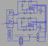
and I hope it helps!in my differential reciever mod the added "gnd break" resistor is just there for amp stability when nothng is connected, not knowing how much margin the amp internal compensation has I would keep the value down to ~< 50 Ohms which only decreases loop gain by ~10%
the higher the value the better from a "gnd loop current breaking" perspective
lower value R turn any differences between amp channel gnds, chassis and exteranl source signal gnd into bigger loop current - higher value causes less current - some of which flows on gnded coax shields
just reposting same pic - no changes
Attachments
Last edited:
Great 5th! Now I can finally see alll the images, will read through again and xompare with my own set up.. which is now exactly according to the schematic posted by JCX! 🙂
And thanks for the Info JCX! Since I am not certain (to say the least) about the margin(s) of my amp design, I guess I'm best of to leave it as it is wit the resistor at 10 Ohms. Seems this mod did the job well and what ever hum/ noise I have left must be dealt with by adressing other parts of my design/ layout.
Thank you very much for looking in to this and for providing schematics and explanations allowing me to implement this, greatly appreciated!!! 🙂
5th,
I've read through your post again looking at the (now visible) schematics, and your explanations seems both consistent and in line with what I've ended up with doing.
Following the accepted logic, If I had disconnected the grounds between the x-over output and amp inputs and connected the ground of the X-over to the star-point, all ground references should be maintained and no loops formed.
I tried this, and that left a lot of noise on the outputs.. strange..
The only explanation I can find is that this left the 0V reference on the amplifier inputs and on the x-over card with different potentials (as in "different" noise and ripple") due to the "roundabout" routing of 0V connections that could be suceptible to hum induction and amplifier power-return influence etc..
But now, with the "differential receiver" mod as described by JCX, I can connect the x-over card to the star-point with no deterioration, in fact, it doesn't mattet if it is connected or not.
So perhaps the ground-breaker, or more correctly, "differential receiver" mod was really not such a last resort after all??
Perhaps It would have been if I had proper separate power and signal returns from my amp cards, but that I have not..
Tomorrow I'll buy some thinner and more flexible wire for the PSU-to amp wiring, and do some properly twisted PSU wiring. Will be interresting to see if that Improves matters further, that and some revised component values in the X-over card for the sub LP filter section.
With a class AB amplifier, as I am sure you have read, the supply rails have half wave sine pulses injected into them, if the amplifier is passing a sine wave.
Just as with high frequency EM radiation, twisting the power cables together helps to reduce this and in doing so helps to reduce the chance of induction based distortion - Self's distortion number 6.
Having an incorrect grounding scheme on the amplifier cards is unlikely to be a cause of noise like you described here.
The splitting of the signal ground and power ground on the amplifier PCB should not have anything to do with ground loops or the creation of noise. It would only present itself as a linearity issue as the power ground injects hash into the signal ground when the amplifier is under load.
If the noise you are hearing is anything other then a humming or buzzing sound created from the mains frequency and it's harmonics, then something else is at fault. Like lots of hiss for example.
Just as with high frequency EM radiation, twisting the power cables together helps to reduce this and in doing so helps to reduce the chance of induction based distortion - Self's distortion number 6.
Having an incorrect grounding scheme on the amplifier cards is unlikely to be a cause of noise like you described here.
I tried this, and that left a lot of noise on the outputs.. strange..
The splitting of the signal ground and power ground on the amplifier PCB should not have anything to do with ground loops or the creation of noise. It would only present itself as a linearity issue as the power ground injects hash into the signal ground when the amplifier is under load.
If the noise you are hearing is anything other then a humming or buzzing sound created from the mains frequency and it's harmonics, then something else is at fault. Like lots of hiss for example.
Hi 5th! 🙂
First of all, the Noise I referrd to was more of a hum-type noise, rectifier and some 50Hz judging from the scope, so fortunately no other mystery noise indicative of something serious! 🙂
And regardin signal VS power grounding on the amplifier card.. After modifying my amplifier cards with the differential receiver, things seems to sound clearer in a way.. or am I imagining things perhaps???
Will be interresting to see what some twisted supply wires will do, it's a common enough advice, but it will be good to see the actual results to be had! 🙂
I don't think you will be imagining things. After all we're talking about adding the differential to sort out and solve a real issue. Any subjective assessment is grossly affected by the presence of buzzes and hum, so removing them no doubt improves the perceived sound quality.
Well, except for the tweeter channel, the hum didn't get much reduced in the mid and sub-channel (only when measured at the amplifier outputs with the inputs shorted) But I was thinking about your experience with regards to distortion..?
Unfortunately, I don't have any distortion analyzer, so I guess I'll never know for sure!
Unfortunately, I don't have any distortion analyzer, so I guess I'll never know for sure!
You do have a distortion analyser, your PC and it's sound card.
ARTA has a spectrum analyser built in as one of it's functions. Also as part of the package you get a program called STEPS, which is designed specifically for one thing and one thing only, distortion measurements.
You've proven yourself to be rather adept at intuition with regards to using programs like this, so download it and have a play.
The first thing you should really measure is the sound card itself. In other words feed the output of the sound card, back into it's line input and measure it.
One thing to bare in mind is that the input will most likely explode if you feed it the full voltage swing the amplifier is capable of on it's output. A series resistor is usually all that's necessary to cut the signal level down as it will form a divider with the sound cards input impedance.
To make any meaningful measurements you have to load the amplifier with something. What you need to do is load the amplifier enough so that it's operating in class AB, rather then class A. If your amplifier is designed to operate as an optimally biased class AB amplifier then this should only require a small load. If it's been biased on the high side then you will need to drive the amplifier harder to bring it out of class A bias. Class A biasing will mask several of the distortion mechanisms, which is why you need to bring it out of this region, otherwise you won't know if they are causing an issue.
From memory, class A biasing will remove all effects of an incorrectly placed tap from the feedback network, induction based distortion and contamination of the signal ground from the power ground. The last two are definitely of interest here as induction based distortion is altered by the cable routing that carries the + and - power to the amp. This you will have some freedom over too, so you should measure and make sure your cable placement is as optimum as it can be. You can see how this affects the performance in real time with the spectrum analyser as you can move the cables around and watch how it affects the performance. If the signal ground is being contaminated by the decoupling power ground this could possibly mask anything else as it can be extremely destructive.
A simple ~8 ohm 10 watt power resistor should be plenty to pull the amp out of class A. Don't worry if you've only got 16 ohms or 4 ohms etc, both will do, just make sure not to exceed the resistors power rating.
When playing around with ARTA do make sure that any settings that control the sampling frequency are congruent. Usually you've got the input and output sampling frequencies as assigned by windows, these can typically be found in the control panel under 'sound' or something. On top of that your sound card could have its own software that controls the hardware sampling rate - I have a situation like this, so to make measurements I have to set the windows mixer thing to say 48khz on both the input and output and then set the sampling frequency in the sound cards software to 48khz too. Naturally you want ARTA to be set to 48khz too.
If there are any differences in sampling frequency something somewhere will perform asynchronous sample rate conversion. If windows does it, it's usually horrible and you will see this on the spectrum analyser as lots of spikes. I've got an ASUS Xonar Essence STX sound card and can happily say that its ASRC is of decent enough quality not to mar the measurements if something is set so that it performs the sample rate conversion rather then windows. If windows does it forget it!
5th,
Thanks again for excellent advice! 🙂
This reminds me that the HolmImpulse software allso has a distortion measurement function.
Now, As I've only used Holm for loudspeaker measurements, I never considered that this could allso be used for distortion analysis of the amplifier it self!
Having said that, I have no idea if Holm is suitable for Amplifier distortion measurement. After all, loudsepaker distortion and amplifier distortion tend to be orders of magnitude apart.
Anyway, your suggestion for using distortion analysis to measure the effects of cable routing in real time is excellent, as re-doing the PSU connection is the next thing on my agenda!
Just bought some thinner and more flexible wire for this purpose. This is 2,5mm2 cable, which I believe should still be adequate even if not as beefy as the 6mm2 wiring I'm running currently.
I have a 16 Ohm/ 25 w resistor, so I guess that should be enough to drive the amp outside class A-operation. And I'll definitively take your advice about adding a resistor to the sound-card input, wouldn't like to fry that! 😱
I allso modified the subwoofer LP filter in the X-over card. Upped the caps from 15/33 nF to 220/440 nF and reduced the resistors from 105k to 7,5k.
That reduced the hum/noise in the sub-channel significantly and brought it down to about the same level as the mid and tweeter channel. That was an easy gain! 🙂
Hmm.. regarding series resistance for measurement connection.. tride to measure the resistance on the mic-imput with my multi-meter.. seemed to start at arround 7M ohm and then just rise... how do I go about selecting the right series resistance then??😕
What make and model of sound card do you have? Sometimes google will find the answer.
Alternatively you could output a low signal level from the amplifier, say 4 volts peak to peak and feed that directly into the sound card. See what input level this gives in ARTA, then put a 10k resistor in series with the output and see by how much the level drops.
Alternatively you could output a low signal level from the amplifier, say 4 volts peak to peak and feed that directly into the sound card. See what input level this gives in ARTA, then put a 10k resistor in series with the output and see by how much the level drops.
Hi,
use a 10:1 resistor ladder to reduce the voltage fed to the input.
Use 10k for the upper and parallel it with a 91k giving an effective 9k01.
Use 1k for the lower. You can feed in upto 10Vac and the output will be almost exactly 10% of the input. The 11mW dissipated in the resistors ensures you avoid temperature effects of the resistance temp co. At 20Vac into the ladder the dissipation jumps to ~45mW
That might just start to show some temp variation. But, the error will still be pretty low.
- Status
- Not open for further replies.
- Home
- Amplifiers
- Power Supplies
- A Grounding challenge , please help..