Hi Andrew,
I have pretty much done so, allthough it is a bit further back in the thread.
Everything points to something going wrong once the amplifer cards gets connected to the x-over card. and the measurements show that there are potential differences that can circulate through signal ground..
I have pretty much done so, allthough it is a bit further back in the thread.
Everything points to something going wrong once the amplifer cards gets connected to the x-over card. and the measurements show that there are potential differences that can circulate through signal ground..
you are jumping around confusing your self.
I suggested days ago that you connect and measure one item at a time until you find a problem. I have followed your ramblings and nowhere do I see a methodical approach to identify the first connection that causes a noise problem.
I suggested days ago that you connect and measure one item at a time until you find a problem. I have followed your ramblings and nowhere do I see a methodical approach to identify the first connection that causes a noise problem.
First thing I found was that noise could be reduced by improved magnetic shielding of the toroid. This could allso be measured.
I then established that the individual amplifier channels were fairly low-noise with input shorted and no interconnection on the signal input side.
I allso found that the problem appeared when signal input grounds were connected together, directly, or via. the X-over card.
disconnecting power to X-over card had no effect.
Potential difference was measured between the 3 individual 0V connection points of the main PSU, something that would drive ground-loop currents.
PSU was re-buildt with ONE 60A fast & soft Recovery rectifier, split reservoir capacitors, and singel PSU supply voltage terminals in stead of 3 individual ones for each amp. Removed possibility for 0V potential variations at PSU, and reduced ripple/ noise.
Improved measurements, but did not remove root cause.
Tried putting resistors in series with signal cable screns from X-over to amps, no luck, incorrect implementation of "ground breaker resistor" concept.
Sure, there is some "rambling" as you call it, but if I had past experience with this and better subject matter knowledge, I would have been able to proceed methodically towards a final solution and implement it, probably without having to consult the forum for advice.
To me, and even to some other contributors to the thread, the root cause seems to be ground noise from circulating currents between the amplifier input stages, and implementation of ground breaker resistors has been suggested as a solution.
John has this in his amplifier cards, I don't, he doesn't have a noise problem, I do.
I'm getting to the stage where I will probably implement this, and as this will require quite some disassembly, I will allso re-wire the servo/ protection cards, and probably replace the PSU-to-amp supply wires with a lighter gauge that can be revolved and routed better.
Ater an extensive PSU modification and a lot of measurements and fooling arround with the scope, it's time for a reality check.
Andrew was right; measure the noise on the outputs, can-hear this and that is not much to go by.
Tony was allso right; connect the speakers and listen to what the measurements actually represents.
Hooked the amp up: hum
Inserted the mu-metal strip between the transformer bulkhead and x-over card: BIG reduction of hum in the speakers! it's still there, but much fainter than before.
It seems the PSU mod made quite a difference with quieter rectifier, capacitor split-resistors and a proper star-point.
Perhaps some re-wiring and ground breaker resistors wil get rid of that last little bit of hum? 🙂
Power up one power amp. measure the output noise. short the input of the power amp, measure the output noise. remove the short from the input, did the noise return to the previous value?
Those two mVac measurements are your references for everything else that you add on.
What are the measured output noise values of just one power amp?
Those two mVac measurements are your references for everything else that you add on.
What are the measured output noise values of just one power amp?
Last edited:
Andrew,
I have done those measurements and described what I foudn here and there, but I havent consistently posted pictures of all the scope measurements I've done, so it is a very good idea to do so here and now as you request.
All three amplifier cards are now connected to the PSU, but I found that it dosen't make much difference as long as the amp I'm measuring on is not connected to the x-over card.
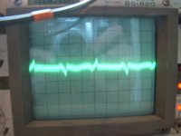
Measurement is done with 1mV/ div
The first measurements shows the first amplifier card with input shorted. the ripple is barely above the noise-floor.
I did this one time before with the other amplifier cards disconnected from the power, and then the ripple was then indistinguishable from the noise-floor.
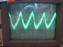
Second measurement is with the amplifier signal input open.
And when shorting the input again, the noise level returned to that seen in the first measurement, so consistency there.
I have done those measurements and described what I foudn here and there, but I havent consistently posted pictures of all the scope measurements I've done, so it is a very good idea to do so here and now as you request.
All three amplifier cards are now connected to the PSU, but I found that it dosen't make much difference as long as the amp I'm measuring on is not connected to the x-over card.
Measurement is done with 1mV/ div
The first measurements shows the first amplifier card with input shorted. the ripple is barely above the noise-floor.
I did this one time before with the other amplifier cards disconnected from the power, and then the ripple was then indistinguishable from the noise-floor.
Second measurement is with the amplifier signal input open.
And when shorting the input again, the noise level returned to that seen in the first measurement, so consistency there.
Attachments
Is there any load on the amps in these measurements? If not, you shouldn't be seeing any ripple on the output. It looks like something else is happening there.
Another thing: a ground loop hum may not show on the scope as it is circulating current in the '0V' scheme.
Another thing: a ground loop hum may not show on the scope as it is circulating current in the '0V' scheme.
Remember that shielding the transformer reduces magnetic fields, but magnetic fields are only a problem where there are loops to pick up the hum. So loops are your problem. Each ground point should have one and only one connection to the reference ground. If your individual amps etc. don't allow for this then you will need to modify them so they do. Remember that a stereo arrangement may have two sets of grounds, so you end up with loops which a mono amp would not have.
No, there is no load on the amplifier output here John.
I'm not sure I follow you right here.. if I have ground loop hum, I would assume it would manifest it self as hum on the output as well? and the other way arround, any ground loop that dosen't cause hum and noise on the output, isn't really any problem? 🙂
I'm not sure I follow you right here.. if I have ground loop hum, I would assume it would manifest it self as hum on the output as well? and the other way arround, any ground loop that dosen't cause hum and noise on the output, isn't really any problem? 🙂
Remember that shielding the transformer reduces magnetic fields, but magnetic fields are only a problem where there are loops to pick up the hum. So loops are your problem. Each ground point should have one and only one connection to the reference ground. If your individual amps etc. don't allow for this then you will need to modify them so they do. Remember that a stereo arrangement may have two sets of grounds, so you end up with loops which a mono amp would not have.
DF96,
That makes perfect sense to me, and probably describes my situation quite well!
My improved PSU reduced issues that would manifest it self in ground loops, and the mu-metal reduced stray fields that can be picked up in loops, but they are evidently still there.
This is why I'm now contemplating how to best implement the "ground break resistor" approach in the input stages most helpfully described by John and JCX.
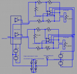
maybe you want to see the multichannel schematic
there is only 1 "gnd clamp" since you are keeping each amp Board gnd, Safety gnd conneciton in heavy wire
the "loop breaking" only occurs between the XO PS gnd and the Chassis/Safety gnd - when just looking at the gnding/Safety gnd "story"
the signal gnd (= XO gnd) is sensed by each amp's new differential input and the (input signal, signal gnd) pair at each amp "differential input" gets "translated" to each amp board's dirty gnd
the theory is that the added 12K "measures" the local amp board gnd and helps cancel the difference between XO gnd at the new "diff gnd" input at the ~10 Ohm R
for the differential reciever function the 10 Ohm R is't required - its only there to keep the amp gain in control when the input isn't connected
we assume any common impedance/induced errors in the system gnd wiring have such low impedance that the 10 Ohm R represents a "large" impedance
I should have said that the "ideal" point on the amp board gnd for added 12K is nearest the load gnd exit from the board - after all what you really want the amp to control is the difference V across the speaker
Attachments
Last edited:
Hi,
how many mVac of noise does your DVM show when the input of the single powered Power Amp is shorted?
How many mVac of noise does your DVM show when the input of the single powered Power Amp is open?
Expect <0.05mVac for the shorted condition. Expect <1mVac for the open condition.
You might as well measure output offset while you are there.
You could measure all three Power Amps to see if they produce consistent results.
Now connect two Power Amps and measure the mVac of noise at the outputs of both powered Amps.
JCX,
Thank you very much for taking the trouble of making an extended schematic and for explaining the function of the extra 12k resistor! Believe it or not, I'm actually starting to see how this works! 🙂
And thanks for pointing out the ideal connection point for the 12k resistor. It really is given from your explanation, I'm not sure I would have seen that my self without having it pointed out to me!🙂
In Bob Cordell's book, the breaker resistor value is specified at 4,7 Ohms, so based on that I should guess that 10 Ohms is a conservative and safe value?
Besides, I have a bag full of those, so 10 Ohms should suite me fine!" 🙂
Now, after this, there's really only one detail I'm uncertain about.
Looking at the shcematic of my amp, R1, R2, and C2 is connected to the board ground together with the current input ground point. Should these components allso be connected to the "new" input signal ground, or can they be left as is?
assuming the only problem is low audio frequency I don't think you would need to change these
the differential input function does degrade when the RF filtering starts rolling off the + input more but it shouldn't cause any audio frequency problems
again I want to emphasize that the outputs from the XO board should be fully buffered -any series R from a level matching pot will change the divider ratio and you won't get the differential cancelling
Hmm yes, allmost forgot about that one.. say, for the amp-cards driving the subwoofers, would a doubling of the C1 capacitor do the trick? A subwoofer channel with a sub-filter would be pretty useless! 😀
Well, there isnn't a dedicated buffer-stage at each output as such, just an op-amp filter- or equaliser stage, with a 200 ohm resistor in series with the output connection point.
Any level adjustments are however made with variable gain stages which are "innboards" of the last filter stages feeding the outputs.. Hope this will be OK?
Don't know if this falls in under the terminology "fully buffered"?
Last edited:
the 200 Ohm series R likely were included to protect the op amps from shorts and to isolate them from load C
if you keep them then you have to recalulate the + input divider ratio to match the feedback R ratio
R_new = ( 200 + 470 )* (12 K / 470)
if you keep them then you have to recalulate the + input divider ratio to match the feedback R ratio
R_new = ( 200 + 470 )* (12 K / 470)
Well, that gives me a value of 17.1K.. Darn.. and me who just happened to have a bag full of 12k resistors as well! 🙂
Anyway, good thing you asked again, and good thing I mentioned the 200 Ohm resistors! 🙂
The only uncertainty left then is the capacitor value for the sub-channel..😕
Anyway, good thing you asked again, and good thing I mentioned the 200 Ohm resistors! 🙂
The only uncertainty left then is the capacitor value for the sub-channel..😕
Last edited:
I thought I'd chime in here too as I've had some experience with this also, 6x channels in the same case and no hum either. I also had another form of current looping through the signal grounds that didn't cause hum, but significantly destroyed the distortion performance. Anyway here goes.
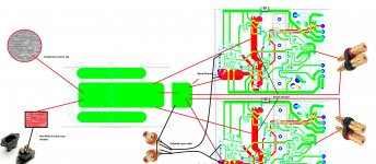
Excuse the huge image.

With regards to the PCB schematics, green = copper top, red = copper bottom. As you can see there are two thick red traces, these are the two ground connections presented by the amplifier PCBs. They are labelled signal and power ground.
The big green stuff in the middle that looks a bit like a Star Trek runabout, represents the filter caps. The end of the central trace is the ground connection point used for the power ground, or any other return current that is 'dirty'. I have then taken a thick piece of wire off of power ground and soldered it to a small piece of PCB. This piece of PCB I use as the signal ground. Signal ground has connected to it, the signal ground return from the amplifier PCBs and the signal return from the loudspeaker terminals.
A shielded cable attaches to the input point on the amplifier PCBs with the shield soldered directly onto the signal ground. The other end of the shielded cable attaches directly to a phono socket. All the phono sockets are mounted to a piece of aluminium, which is affixed to the back panel of the amplifier, which is made out of a piece of ply wood. I then take a single wire from the aluminium plate and connect it to the signal ground on the PCB.
Here is an image of the inside of the case and here is a link to the build thread that illustrates the end performance.
It should be noted, although obvious I think from the picture, that the transformer is in a separate MDF box.
Excuse the huge image.
With regards to the PCB schematics, green = copper top, red = copper bottom. As you can see there are two thick red traces, these are the two ground connections presented by the amplifier PCBs. They are labelled signal and power ground.
The big green stuff in the middle that looks a bit like a Star Trek runabout, represents the filter caps. The end of the central trace is the ground connection point used for the power ground, or any other return current that is 'dirty'. I have then taken a thick piece of wire off of power ground and soldered it to a small piece of PCB. This piece of PCB I use as the signal ground. Signal ground has connected to it, the signal ground return from the amplifier PCBs and the signal return from the loudspeaker terminals.
A shielded cable attaches to the input point on the amplifier PCBs with the shield soldered directly onto the signal ground. The other end of the shielded cable attaches directly to a phono socket. All the phono sockets are mounted to a piece of aluminium, which is affixed to the back panel of the amplifier, which is made out of a piece of ply wood. I then take a single wire from the aluminium plate and connect it to the signal ground on the PCB.
Here is an image of the inside of the case and here is a link to the build thread that illustrates the end performance.
It should be noted, although obvious I think from the picture, that the transformer is in a separate MDF box.
Attachments
5th,
Allways glad to have you chiming in you know! 🙂
Quite a few pages that thread, but I've started reading in to it, it will be interresting to see what you encountered and how you solved it! 🙂
Allways glad to have you chiming in you know! 🙂
Quite a few pages that thread, but I've started reading in to it, it will be interresting to see what you encountered and how you solved it! 🙂
5th,
First of all, I must say that the source of your 3rd harmonic problem was quite surprising! It must have been great to finaly identify and solve that, well done! (niot that I understand half of the other things that were investigated and tried...)
The first thing I notice, is that you have separate star-point returns for the rail decoupling capacitors, signal ground and loudspeaker returns.
My amplifier cards only have one return for all three, which is not according to what is defined as best practice according to some..
I have allso read that a separate rail decoupling cap return should not be returend to the main starpoint, but to a point "upstream" of this, but it seems to work for you, especially considering the distortion figures you were finally able to obtain!
If I had signal ground disconnected from "power" ground. i.e. loudspeaker and decoupling cap return on my cards, and provided signal ground to the input and feedback shunt resistor ground points through the x-over board connection wire screens, and having the x-over board ground connected to the star point, I should in theory have the same grounding layout as you have?
This is of course assuming that you have the feedback shunt resistor and input ground connected directly to your signal ground with no "ground breaker resistors" etc..
- Status
- Not open for further replies.
- Home
- Amplifiers
- Power Supplies
- A Grounding challenge , please help..